KHD T312
 |
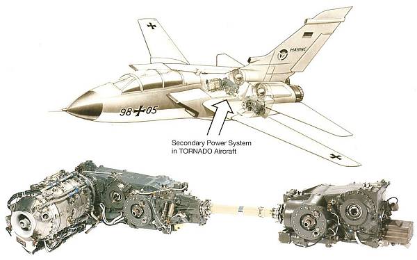
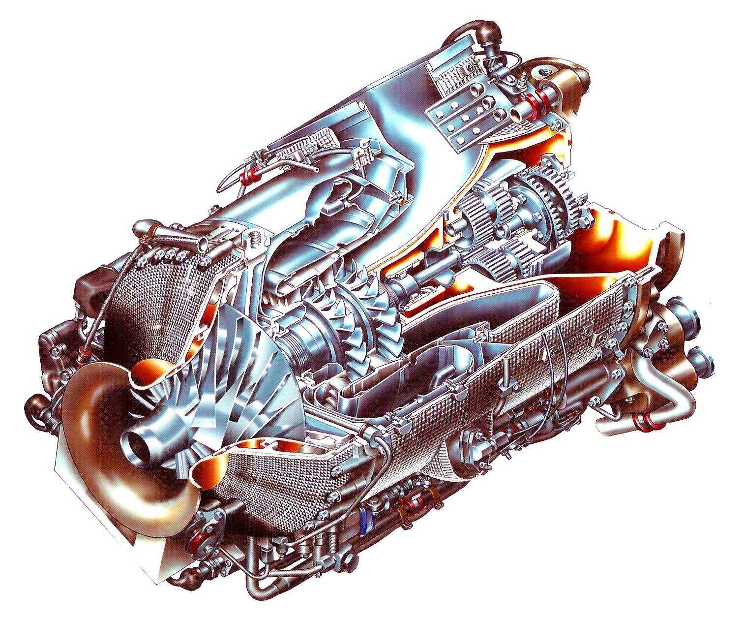
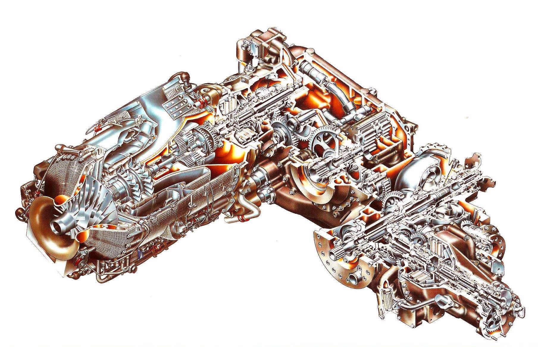
The KHD T312 is a somewhat less common small turbine engine that had been designed in the late 1960s / early 1970s by the german engine manufacturer Klöckner-Humboldt-Deutz AG as an APU for the european Multi Role Combat Aircraft (MRCA) Tornado:
 |
 |
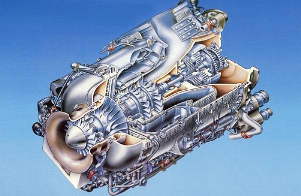
It has evolved from its predecessors, the T112 (ten prototypes - APU for the german VAK191B VTOL experimental aircraft), designed in collaboration with Bristol Siddeley of the UK (which 1966 became part of Rolls Royce), and the air compressor T212 (three prototypes - experimental power plant for the DO-32 / DO-34 Kiebitz). The engine is quite complex and of a peculiar design for a single shaft layout, featuring a hot end drive shaft. The only other engine that springs to my mind which is designed this way is the russian 2PW8. Yet, when looking at the sectioned drawing of the T312 above, the twin axial turbine arrangement may suggest that this engine originated from something that featured a free power turbine, only coupled gas-dynamically to the power head. Well, this will probably always stay a mystery, as well as the question why the dual axial turbine arrangement wasnt replaced by a single radial stage...
Early last year (2013), I was lucky to spot one of these rare, early units close to Munich. It was part of a private collection, located at the ultralight airfield of Wasentegernbach. Straight ahead I contacted Karl, the owner of the collection, and asked him if he would possibly consider a trade of his T312 which he at that time at least did not refuse. Later on, while I stayed a few days in this area anyway to work on an Ultrasport 496 turbine conversion, I visited Karl and had some very interesting coversation (what else would you expect when two aviation / turbine engine enthusiasts meet for the first time). I still had a very nice Isotov GTD-350 of the Mi-2 helicopter in museum condition that I had no real use for (too big for my average collection size and Im not the boating type of guy...):
 |
So I offered Karl this machine as a trade for his T312 -- which he agreed upon.
This way, I got hold of my first T312, a very rare, early version, S/N 108 (most likely but due to a scratch on the badge not 100% identifyable):
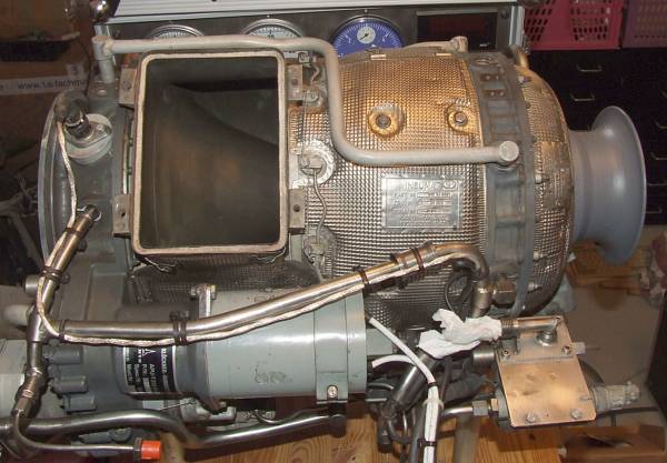 |
This machine was a little bit dusty and had some dents and distortions in the plumbing but this was easily corrected.
 |
...next to my trusted old flow bench...
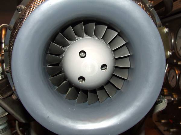 |
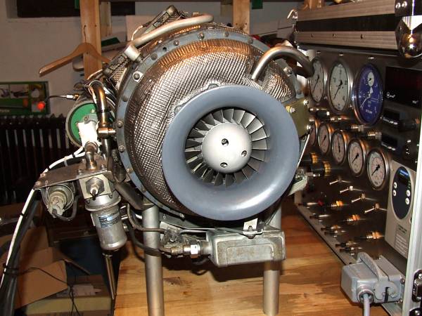
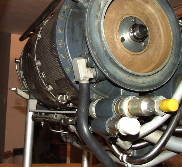
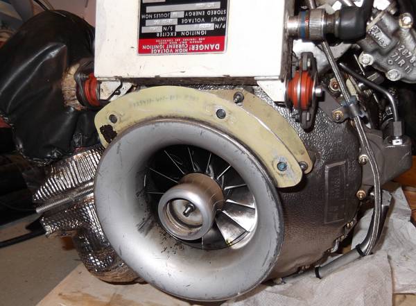
The axial compressor - aggressive!
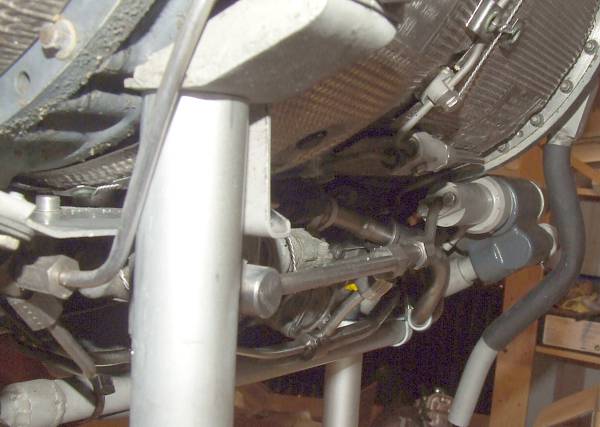 |
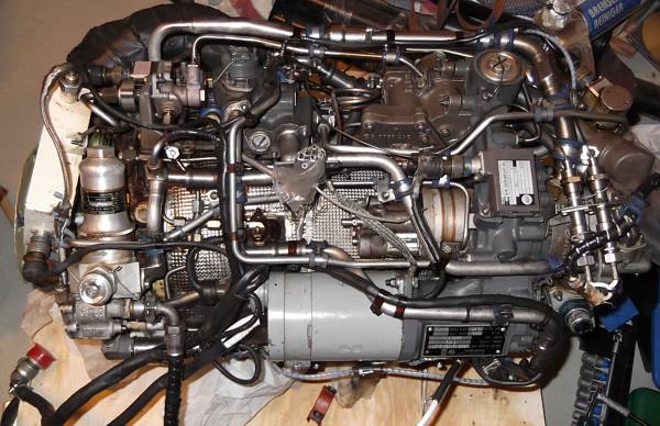
A lot of stuff is arranged around the periphery of that engine -- even on the early units.
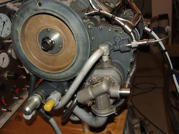 |
If you really want to attach something to that enigne, it has to go here. The capped ports are associated to the lube system.
 |
As you see, still some cleaning needs to be done. After I machined the three stands to place the engine level, I considered it a very good idea to crank it up on the starter (who wouldnt - Ive done that before while the engine was located inverted on some styrofoam). The result was a mess of preservation oil sprayed all over onto the basement wall... Now that the engine was arranged correctly, the oil that remained inside, accumulated at the drain port and the two scavenge pumps did their job - building up enough pressure to blow off the return line cap -- with easily imaginable results. The really embarrasing detail about this mishaps is that beforehand, I thought about that possible complication but completely forgot it when I saw the engine on its three feet and had the power wires to the starter in my hands... Anyway, the positive thing to be drawn from this smelly and messy mishaps is that the engine had been properly preserved during the years of storage...
 |
Finally, the hot section appears to be in pretty decent shape...
Actually, the desire to get hold of one of these units started much earlier. Since the manufacturer KHD isnt located too far away fromy my place (if the stars had been arranged differentlyfor me, I might have actually ended up there as an engineer/scientist), several former or even current employees of that company live in my vicinity, and some of them recycled time or cycle-expired components of their engines by selling them as collectibles at flea markets and the like. This way, I almost obtained a complete rotor of the T312, only less the tie bolt, the compressor shaft and nut. This almost complete rotor eventually found a new home somewhere in South America (if I remember correctly...), long before I received the first complete T312:
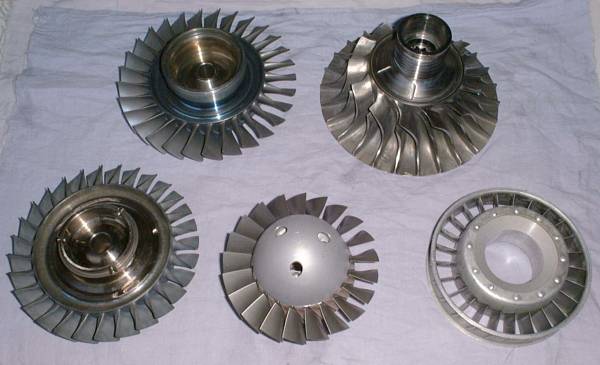 |
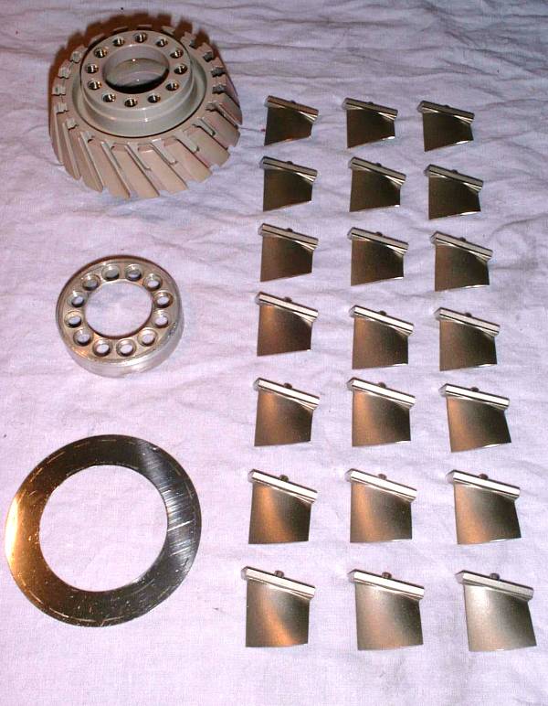
All the stuff that I was able to obtain, over several years...
 |
 |
 |
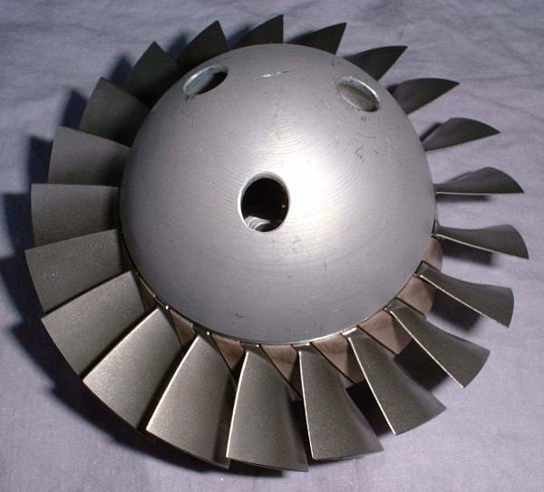
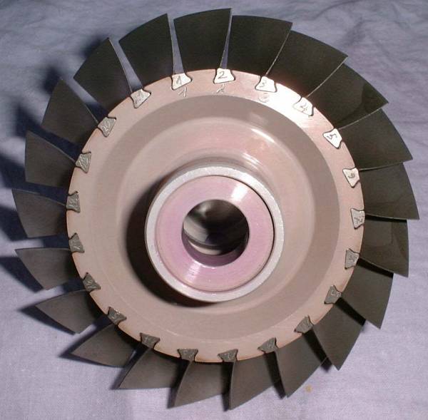
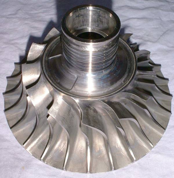
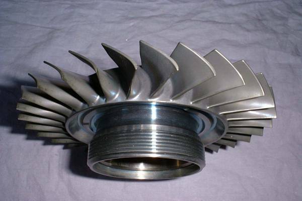
A beautifuly axial compresoor impeller with detachable, individual titanium blades (see the photos further down the page).
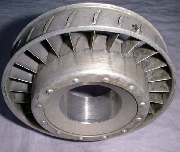 |
The axial compressor diffusor -- a masterpiece of brazing/welding work!
 |
The radial compressor impeller, machined from a titanium forging.
 |
 |
 |
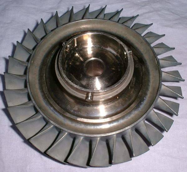
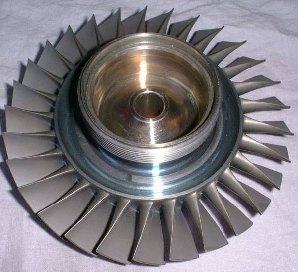
These three photos showed the first stage turbine wheel, cast of MAR-M 247 and afterwards hot-isostatic presses (HIP) -- state-of-the-art at the time of manufature.
 |
 |
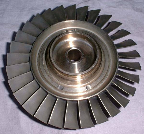 |
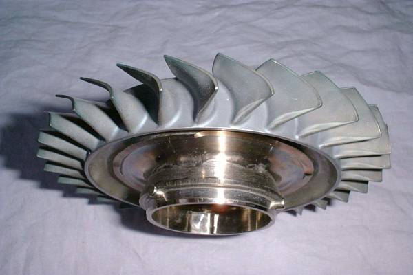
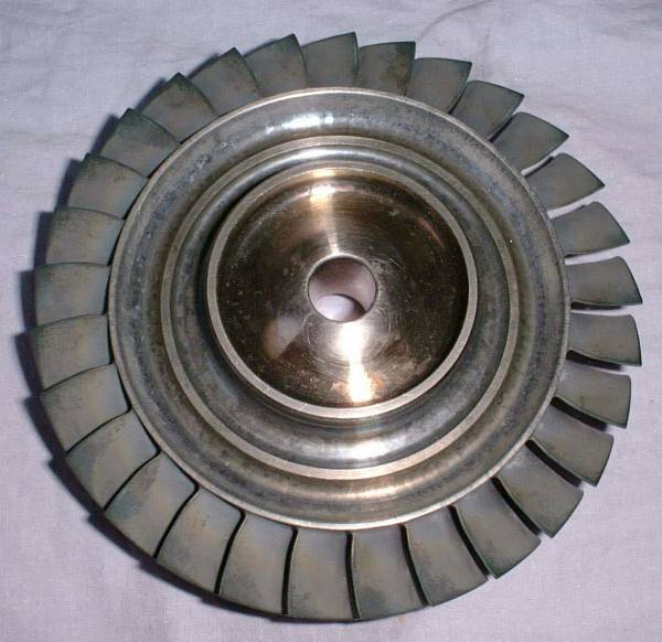
The second stage turbine wheel. I dont know for sure the alloy its made of -- its got a slightly different hue than the first stage wheel so it may be cast from Inconel 713LC but Im not sure about that. These turbine wheels were not changed on the evolutionary versions of the engine so you can consider them to look the same on the engine(s) presented further down this page...
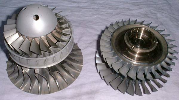 |
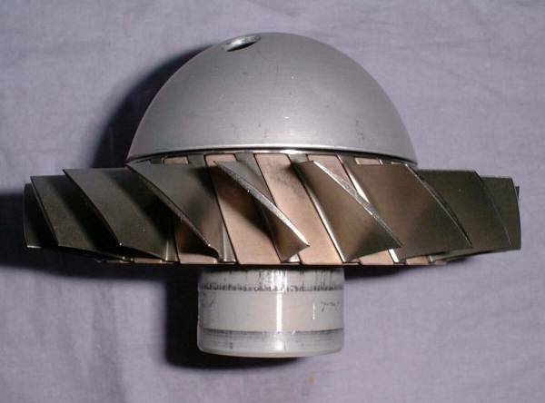
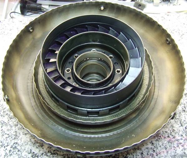
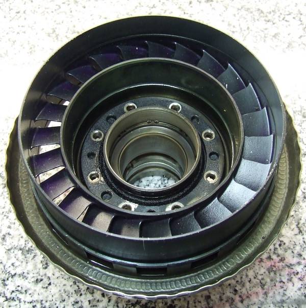
Thats the way the individual parts would be stacked in the engine.
 |
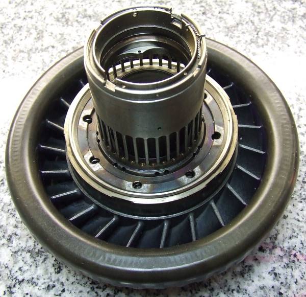
I simply couldnt resist to disassemble the axial compressor...
 |
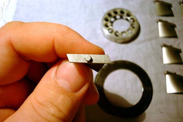 |
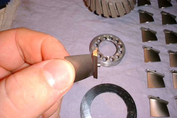
Just enjoy the details of these delicate axial compressor blades...
The particulars of this early engine are:
|
Some information on these engines can also be found here!
The Evolutionary Version -- T312-04
 |
Work on the improved version commenced in the late 1980s after some experience with the then standard versions under hot ambient conditions that made the air forces who utilized the Tornado decide they need a more powerful APU. The task for the engineers at BMW / Rolls Royce (who had taken over the gas turbine department of KHD) was difficult enough - the evolutionary version had to be based on the pervious models in forms of a conversion package to keep the expenses within reason.
 |
The requirements quickly made clear that a slight increase of the pressure ratio with the accompanying increase of air mass flow would provide the specified power output. The question was only how to achieve that increased pressure ratio, since the two stage compressor wouldnt permit another axial booster stage (which is a common practice if an existing radial compressor design has to be pimped a little - compare the Williams WR2-6 / WR24-7-2 for example). Since the engine RPM couldnt be changed, a more modern, transonic radial compressor would have to be much larger in diameter than the existing radial impeller, leaving only little space for the diffuser. Yet, that was the route the engineers at BMW / Rolls Royce chose, maybe also because they had accumulated some experience with high performance radial compressors on their UAV turbojet engines T117and T128. Nevertheless, the integration of a highly efficient transonic diffuser in the available space was a true masterpiece of engineering! Even though the increased pressure ratio resulted in a slight mismatch in the turbine stages, the complete engine can be cosidered one of the most efficient units of its class. I would love to peek in the original design documents to actually get an idea of the individual efficiencies of the turbomachinery stages...
Here are the specifications of the evolutionary version:
|
Now that those airforces that had the Tornado in their inventory, eventually retire the fleet with the advent of the Eurofighter Typhoon, more and more of the T312-04 APUs find their way into private ownership of collectors, turbine enthusiasts and those who intend to give them a second life in experimental aviation. The units that "surface" these days mainly originate from the Royal Air Force Tornados and most of them can be considered phased-out due to time expiration, malfunctions or defects. I've got two of these machines in my basement that I'm overhauling for a friend, and both of them clearly show problems, one suffered a catastrophic bearing failure at the starter drive shaft gear, distributing metallic swarf throughout the gearbox, the other shows an oil leak at the compressor bearing cavity and some (possibly tolerable) cracks at static components in the compressor area. My objective is to make one good engine out of these two. Yet, the suitability of the T312 for an application in the experimental aviation sphere still has to be proven.
Below, some photos of these engines follow:
 |
The engine upside down as it arrived in my basement. On the left the ignition exciter box (whitish), in the lower center the starter motor (grey).
 |
The compressor intake.
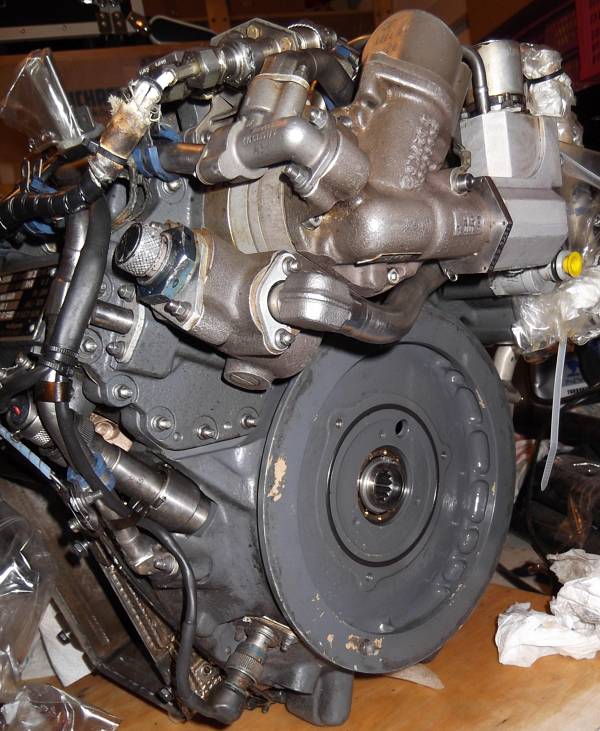 |
The drive pad needs an oil seal since in the original application, it interfaces to a hydraulic multiple disk clutch thats running in an oil bath and hence doesnt need to be sealed off.
 |
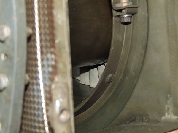
Through the exhaust port, some of the second stage turbine blades are just visible.
Starter motor and associated part of the gearbox. Also the designation badge of the engine. At the far left, the removable magnetic chip detector plug is visible.
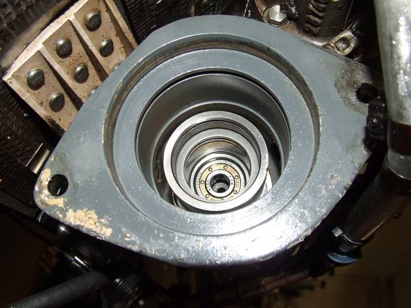 |
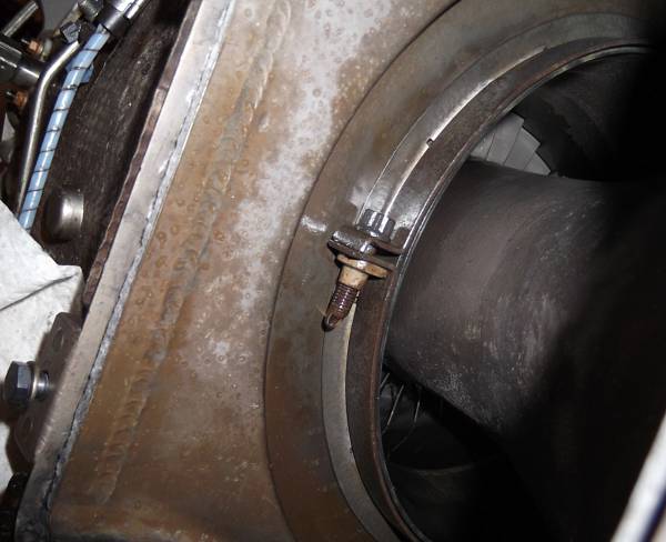
The starter flange without the starter motor and the sprag clutch members. Only the clutch cylinder and support bearing are still in place. Im considering a method to attach a starter generator here without a clutch mechanism, yet some kind of shearing device should be implemented to decouple the starter generator in case its rotor gets stuck. Ive already got someting in mind...
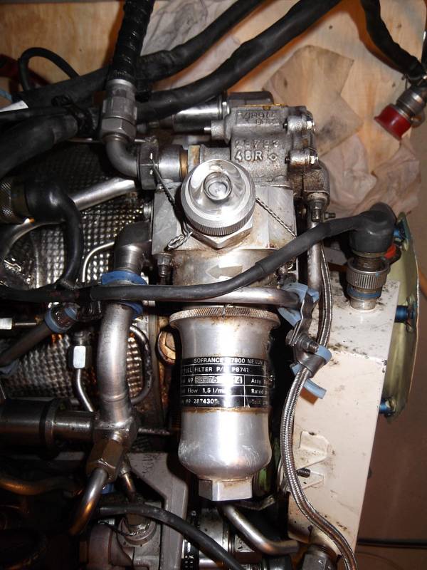 |
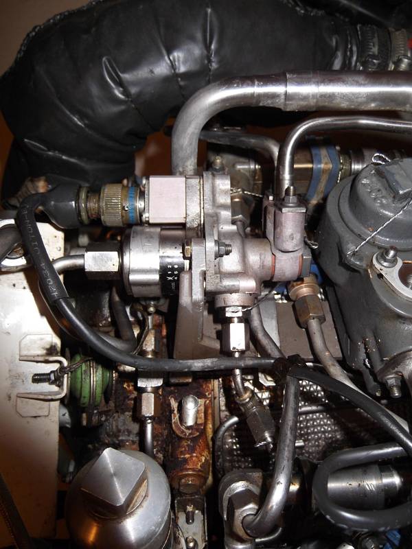
The main fuel filter and sight glass.
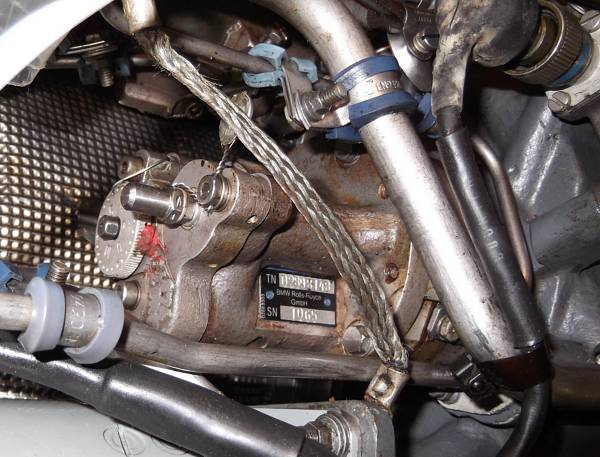 |
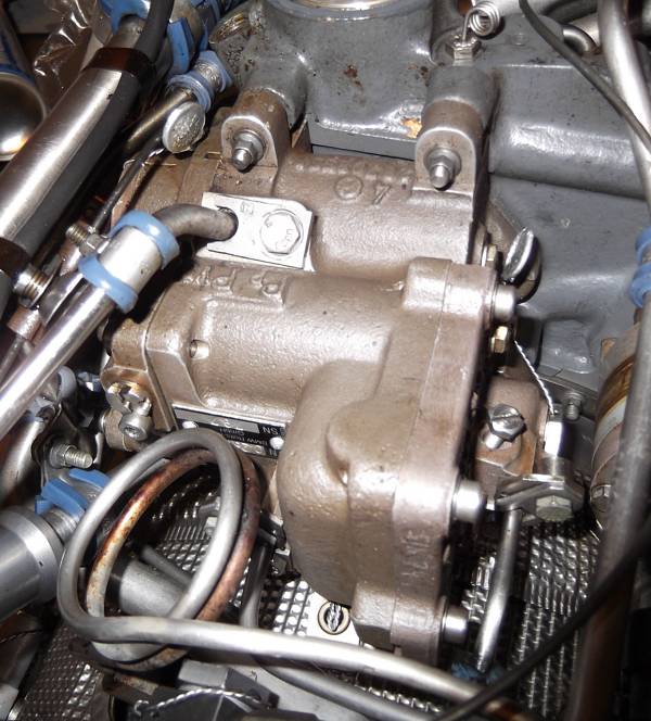
Thats the high pressure fuel pump. It also includes a flyweight unit to signal RPM as a pressure value to the main fuel control unit. The manual that I was able to source unfortunately is not completely clear about the internal working details of the fuel metering system.
 |
Thats the fuel control unit, surprisingly arranged remote from the fuel pump on the engine gearbox. Its just a hydraulic / pneumatic unit, no mechanical drives or electrical signals are connected to it.
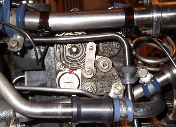 |
A side view of the fuel control unit. Some funny slotted gate adjustment mechanism placed here.
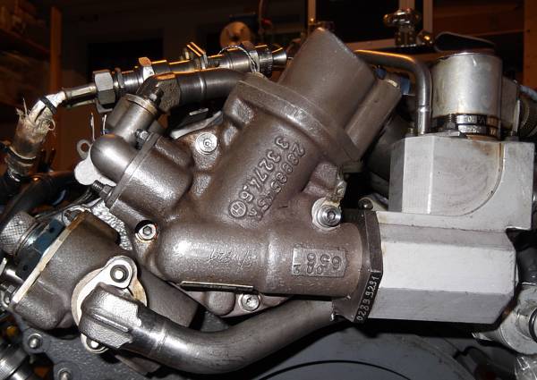 |
A view onto the lube pump. It contains a pressure and two suction pump elements along with several valves. At the right, theres a fuel pressure operated oil intake valve that prevents draining of the lubrication system while the engine is not running.
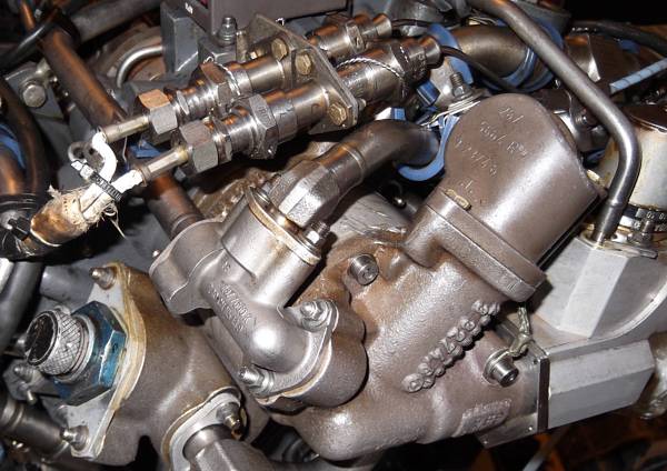 |
Another photo of the oil pump area. Its mounted vis-a-vis to the fuel pump and driven from the opposite shaft end of the same gear. Here also the fire wire connectors and the chip detector are visible.
 |
Thats the valve block of the lubrication system. The cover with the square drive caps the main oil filter. To the left, the start fuel valve is just visible. Since the APU also provides hydraulic pressure of approx. 30 bar to engage the hydraulic clutch in the right-hand coupling gearbox, the lube system is quite complex. This pressure can be disabled during startup by a solenoid valve.
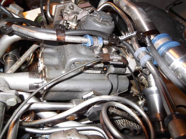 |
One more close-up view of the valve block and the plumbing around.
Even just a preliminary external inspection of the engine makes completely obvious that working on this complex machine will not be far from a nightmare.
 |
One of the two engines that I received showed some ugly coked oil crusts below the compressor casing, indicating a leak in the compressor bearing area. So disassembly of at least the compressor section would be required.
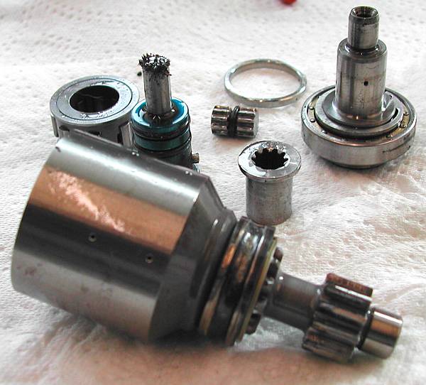 |
The other one revealed a lot of metallic swarf at the chip detector magnetic plug and all the shaft couplings of the starter motor looked pretty much worn.
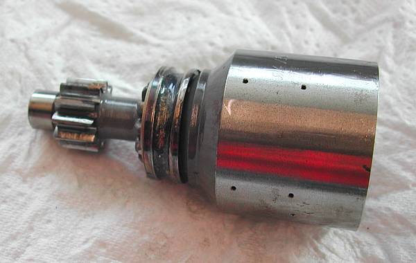 |
Further disassembly (which was fortunately possible without stripping anything else) indicated a completely disintegrated bearing at the starter gear shaft. This catastrophic finding renders at least the gearbox and lube pump of that engine useless. Yet, the power section components may still be in acceptable condition which will have to be checked at a later time. A chat with one of the engineers who was employed at BMW / Rolls Royce during the time the T312 was designed and later on overhauled, indicated that this failure was not uncommon. Its related to the high speed the starter gear is spinning at (round about 30krpm) and the considerable diameter of that particular bearing.
After these findings, I decided to continue with disassembly of the compressor of the engine with the oil leak:
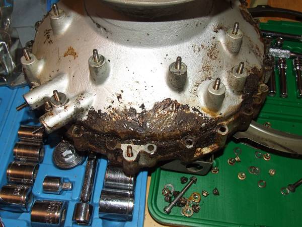 |
Still more coked oil residues at the magnesium alloy compressor cover. Cleaning these components will be a task of its own...
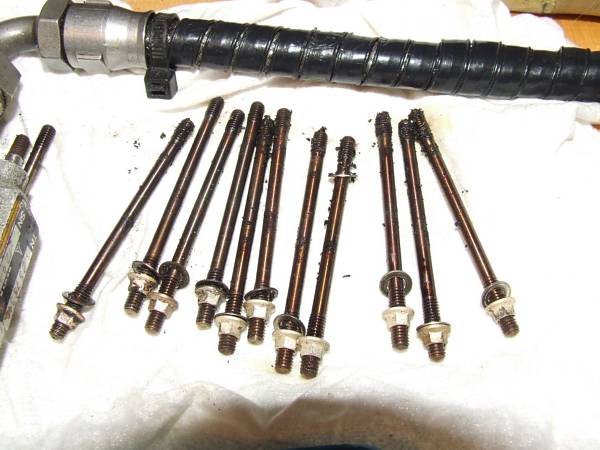 |
Even the threaded studs were all crusted with oil coal and many came out with the fixed end.
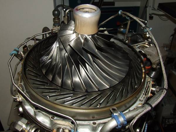 |
Finally, the radial compressor is apart. A beautiful, machined titanium impeller and a delicate transonic diffuser with splitter vane design are exposed.
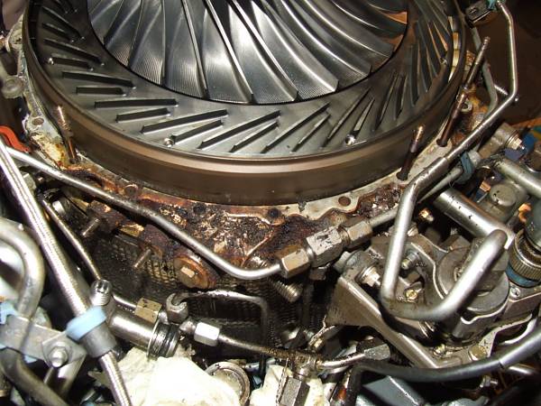 |
Here the oil must have leaked through. Amazingly, all the flanges arent sealed by dedicated rubber, paper or metal gaskets but just by surface sealing compound (Hylomar). Exposed to the extreme pressure/heat conditions, this seal may eventually deteriorate and cause the leakage.
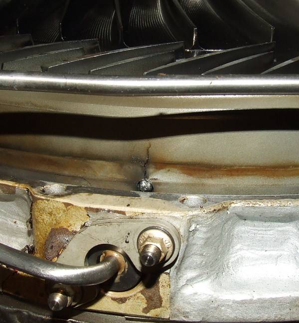 |
Moreover, a crack was found in the axial diffuser shroud ring. Since this component is not a structural one, the crack may be tolerable but I decided that if the power section of the other engine is in more decent condition, Ill just swap the two...
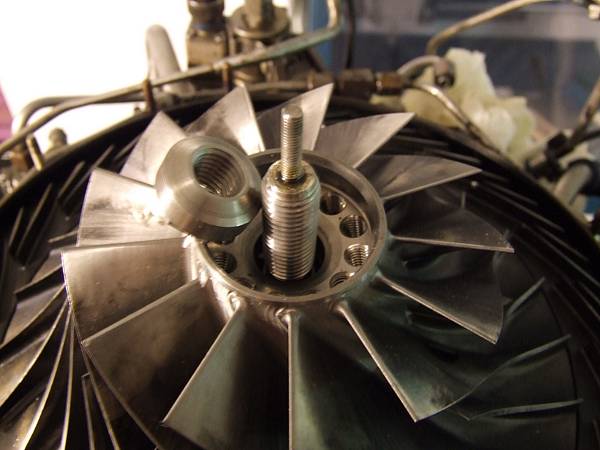
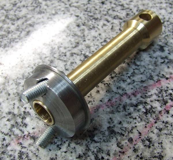
Further disassembly was delayed by the neccessity to construct a hydraulic puller to pre-tension the tie bolt that runs all the way through the engine rotor and holds it together. The nut on this bolt is not supposed to simply be tightened to a specified torque / angle, but the tie bolt must be tensioned to 50kN, then the nut will be turned home hand-tight and after that the tensioning force will be released. Disassembly requires this procedure to be executed reversely. This method of assembly prevents the tie bolt to be (elastically) twisted, only axial force will be transferred through it.
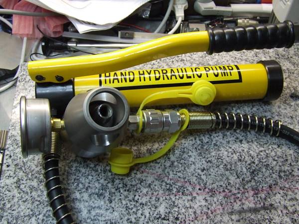 |
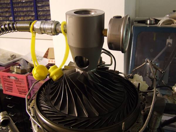
And thats what the tool looks like: A small off-the-shelf manual hydraulic pump is attached to specifically machined, co-axial hydraulic puller assembly that hosts a pressure gauge at the other side. The surface areas are chosen so a pressure of 500bar will result in the specified 50kN of force.
 |
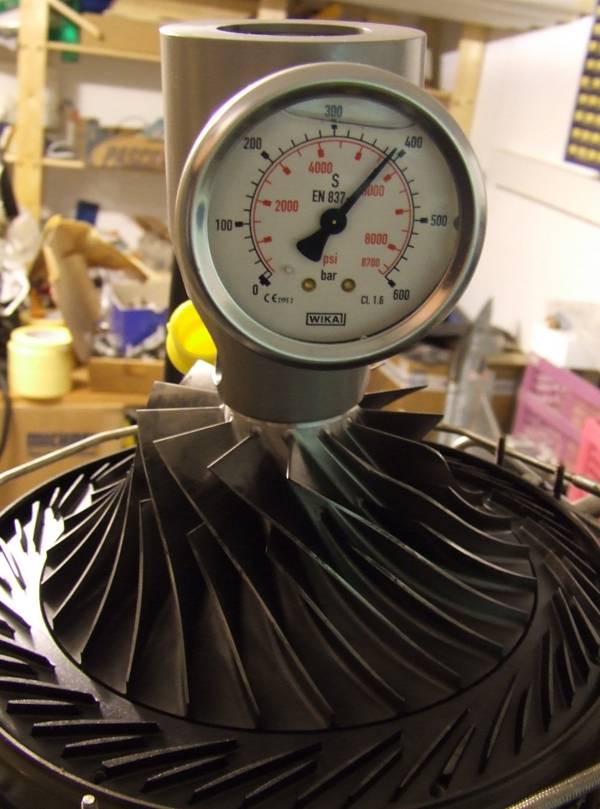 |
The nut actually came loose at slightly below 400bar, which may be an indication for some settling in the rotor assembly (or improper tensioning of the tie bar during the last overhaul or possibly wrong information regarding the required tensioning force - I guess Ill have to verify this before reassembly).
 |
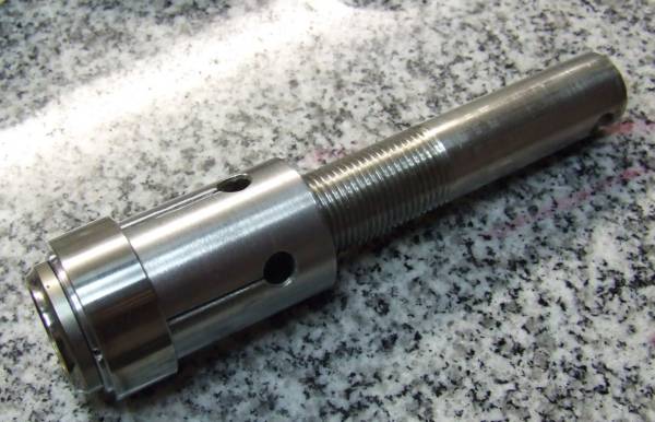
And voila -- the nut is off. Thats really an elegant method to tighten rotating assembly bolts, yet it requires the avilability of special tooling. Immediately, the next special tool was required -- a puller that attaches to the balancing weight threads (drilled at an angle) and uses the annular space between the tie bolt and the compressor to push the compressor off its shaft. Since this annular space is quite small, an ultra-fine thread was cut (something like M15x0.5).
 |
The compressor was quite a tight fit but with some grase and some more violence, it finally came off...
 |
Just for curiositys sake, I decided to take a photo of the T312-04 compressor next to one of a Solar T-62T-32 since these two engines are approximately in the same power class -- guess which one is more modern... ;-)
Yet, still the compressor bearing casing wouldnt come off. I assumed that the inner race of the compressor bearing, which is of the four-point agular contact variety with a split inner race, kept the casing from sliding off freely.
 |
So I machined another special tool to pull the front half of the compressor bearing inner race from the shaft. Fortunately, this race has got a recess machined to be able to grab it with a puller.
Unfortunately, even with the bearing race removed, the casing wouldnt move by more than a few tenth of a millimeter. So I had to face what I intended to avoid by all means -- in order to disassemble the compressor bearing seat area, all the accessories, tubes and pipes around the power section of the engine need to be removed. Then the insulating blankets must be unwired and removed just to gain access to the locating pins of the torus and the combustor liner...
I decided to take my time and just work an hour or two every weekend on the machine, and after some time I managed to get it apart:
 |
 |
The compressed air passages in the bearing casing casting.
 |
The heat shield between the torus assembly and the compressor bearing casing.
 |
Through this annular space, the oil has to drain back to the oil scavenge pump.
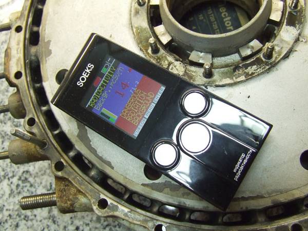 |
And now for something really ugly: A few of the magnesium alloy castings that are exposed to elevated temperatures, contain some thorium. They are mildly radioactive, my Soeks Geiger Counter reading 14 microsievert per hour (yet, this instrument is calibrated on the energy spectrum of 137Cs, so the figures will have to be scaled). Thats not acutely dangerous but I wouldnt store the components under my bed... Its amazing that there arent any hints notifying the personnel working on that engine about this fact.
Simple handling of these parts wouldnt pose much of a hazard but if surface rework is required and abrasive processing is accomplished, inhaled dust can be quite dangerous.
 |
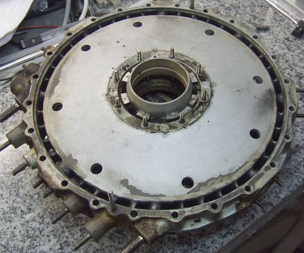
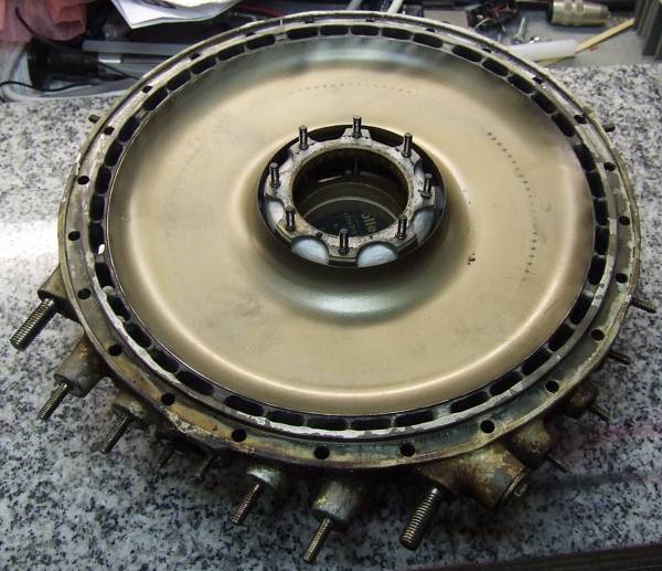
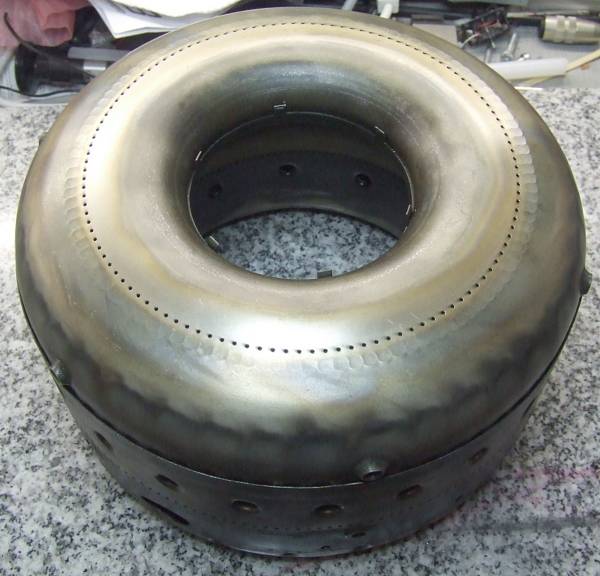
Here the assembly of NGV and the torus that turns the hot gas from the reverse flow combustor around 180°, is shown. To tell from the hue of the NGV, I guess its made of a cobalt base alloy to withstand the extreme temperatures in this area.
 |
The NGV with the inner lip of the torus.
 |
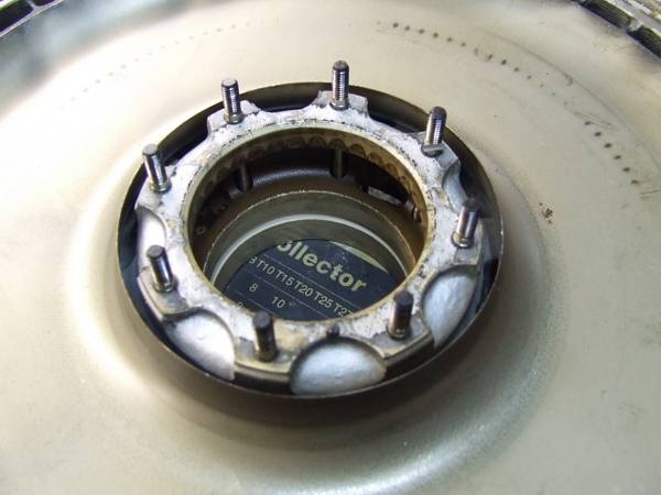
The NGV, this time from the front together with the compressor bearing retainer and the bearing outer race still in place. The axial spokes arent part of a viscous vibration damper but just provide a passage for the lubrication oil to drain from that area. One of the two oil injection nozzles is visible just below the outer bearing race.
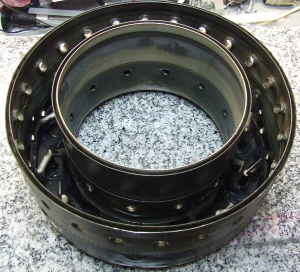 |
The combustor is a quite complex welded sheet metal assembly and is of the reverse flow vaporizing variety.
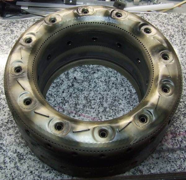 |
Its rear wall accomodates twelve welded hook style vaporizers
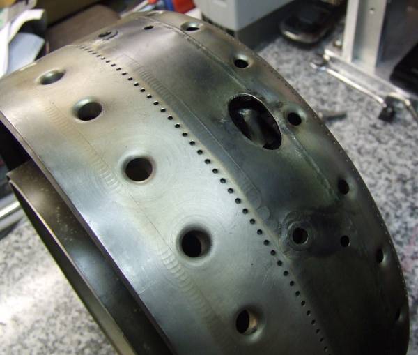 |
This egg-shaped orifice interfaces to one fo the three ignition fuel nozzles. One of the vaporizers is visible directly beneath.
 |
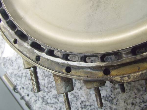
The serrated radius of the torus fits snugly in the slot of the combustor. This way, a layer of cooling air gets blown over the inner wall of the torus. In the flow direction, every five centimeters or so, a row of cooling air holes with a deflection baffle below is located.
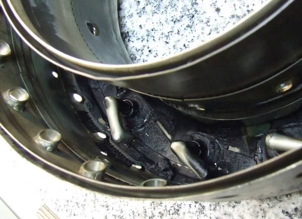 |
The vaporizers are arranged against the swirling direction of the air entering from the compressor. Amazingly, the vaporizers arent discoloured at all, just sooty as the whole rear wall of the combustor. The amount of soot and even lumps of oil coal in this area makes me assume that either theres been a lot of oil burning in there or the combustion in this engine is very rich in the primary zone of the combustor. I guess Ill find out when I disassemble the other engine (or just do a borescope inspection of its combustor).
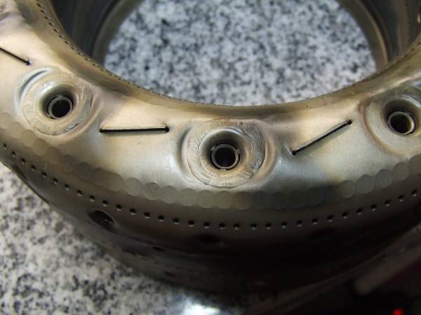 |
The entry area of the vaporizers is not just a plain weld to the rear combustor wall but theres a slot around the tubes while they are attached to the funnel-shaped outer shrouds in only three places. This way, a cooling air layer is permitted to form over the first axial vaporizer tube segment.
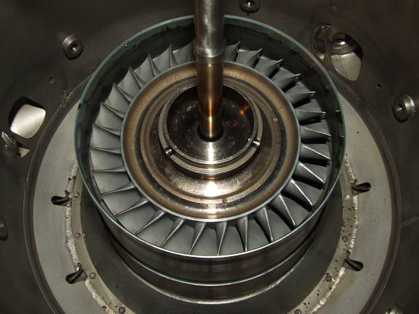 |
Here the first stage axial turbine wheel is shown. These wheels have been cast by a specialist company (Doncasters, Bochum, Germany) from MAR-M-247 nickel base alloy and afterwards they underwent a Hot Isostatic Pressing (HIP) treatment. This procedure closes small internal voids and makes the whole structure more homogenous. The wheels a very fine piece of engineering and is exposed to very severe operating conditions. Calculations revealed that the hot gas that enters the first stage NGV must have a temperature of approx. 1050°C at maximum power. This is intense yellow hot. Respect!
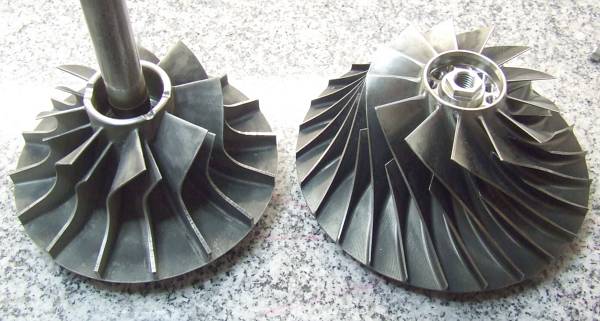
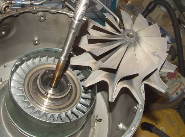 |
I couldnt resist to place a Solar T-62T-32 radial turbine wheel next to the T312. In this application, the single radial stage isnt performing worse than the two-stage axial arrangement of the T312, simply since the blade tips of the radial wheel can revolve at a much higher circumferential speed than in case of the axial variety. Thats the result of a much more benign temperature distribution along the flow path of the blades. Moreover, the surface area of the radial turbine blades is much bigger compared to the axial configuration. Thats the reason why a single radial turbine stage can replace two axial stages in a small engine (i.e. at comparably low pressure ratios). If an arrangement of several turbine stages is required anyway, its very uncommon to use radial wheels because turning the flow around from the exit of a stage to the entry of the next one is very difficult, especially at the high temperatures present in turbines and its also accompanied by high losses.
Thats how far I got with the engines, when theres further progress, Ill post follow-up reports in this place. I hope you enjoyed reading so far!