Solar T-62T-32
(or one most enjoyable week on Cyprus)
News - stories from another trip to Cyprus
Well all this started just short of two years ago when I decided to design an electronic governing device for my TS-21 and Andreass Monocopter engine. It must have been just about that time that Platon found my web site in search for turbine engines that might possibly suit his Ultrasport 496 two-seat micro helicopter. I told him the only engine I could think of that is in the required power range and is readily available and affordable would be the Solar T-62T-32, originally being used in the EMU-30/E 60kVA gensets. Of course I explained to him the shortcomings of this engine, especially the necessity of an electronic governor since it isnt equipped with a hydromechanical one. I also gave Platon the link to an individual in the Netherlands (sorry, forgot his name) who offered such an engine on Barnstormers at a considerable price.
Platon mailed me back and asked if I would be able to design a suitable governor. I had a quick glance at my very preliminary design of the governor for the Monocopter and TS-21 engines and decided that it wouldnt make much difficulty to actually adapt it to any other small turbine engine in that power range. Shortly after this, Platon bought the engine from the guy in the Netherlands, while I continued hardware design of the governor.
I thought about which way to go with the design and since the possibility of field adjustments to the parameters of the governor were one of my major requirements, I decided for a combined digital/analog solution. Hence the governor would consist of two modules, the Turbine Engine Control Module (TECM) which is an analog calculator resembling all the control functions of a small turbine engines hydromechanical fuel control unit (FCU), only doing it electronically:
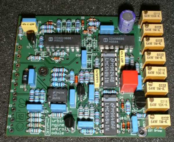 |
As can easily be seen, this unit offers a lot of adjustment pots. In detail they are
- frequency/voltage converter gain
- error gain (proportional)
- derivative gain
- derivative time
- minimum fuel flow
- acceleration limiter gain
- EGT limiter setpoint
- EGT limiter droop (gain)
One of the design features Im most proud of is the instantaneous frequency/voltage converter. Since input to the TECM is a frequency signal from some kind of (electromagnetic) RPM pickup device on the engine, it is necessary to convert this into a voltage signal in order to do the analog calculations. Actually I did some experiments on a breadboard with a PLL circuitry but loop stability wasnt satisfactorily, especially when regarding the adjustment requirements of a turbine engine. Once this TECM unit worked fine on my breadboard, I designed a nice and small PCB for it and had it made by my favorite PCB manufacturer (Ingenieurbüro Ringler, http://www.ibr-ringler.de).
The next tests with the first assembled TECM unit turned out to be very promising and only minor tweaking was required. Now the next question arose - namely the implementation of safety mechanisms that are most important on turbine engines. If for instance the RPM pickup on the engine should go bad or a component in the RPM signal path on the TECM fails, the engine speed will be increased infinitely (actually the acceleration control will to some degree take care of this), but since a startup sequencer was required anyway, I decided to go with a microcontroller which controls all the protection, sequencing and safety functions and as well allows for some debugging. Consequently, the Gas Turbine Engine Sequencer which also houses the TECM, was designed:
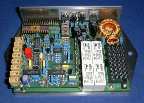 |
It contains all the power circuitry to operate from a voltage range of 8-30V (important when the power supply voltage is being pulled down by the high current drain of the starter motor), provide four high-current relay outputs, two indicator outputs for LEDs/Lamps, two opto-isolated inputs and a special starter switch input that enables the starter/ignitor fuctions by direct hardware link (though they are still to be enabled by the sequencer controller - it only prevents their activation in case of a failure of the microcontroller). The most important output is probably the PWM-controlled throttle actuator driver. All of this system is designed to provide the best safety possible for both the turbine engine and the operator.
The current software version performs a shutdown in any case of malfunction, though the special version for Platons engine will only initiate a shutdown in case of a severe engine overspeed. Any other exceeded engine condition like high EGT, low oilpressure, slight overspeed... will only make a warning light come on but wont stop the engine. Thats since the engine can be expected to keep on running for a certain time even if there is a malfunction and will possibly allow the pilot to emergency land his helicopter under power. The reason that a severe overspeed condition is actually an indication for a shutdown is that in this case an engine rotor burst is to be expected, and an uncontained engine failure may cause such bad damage to the helicopter that an autorotation landing wouldnt be possible anymore.
A future version of the governor will also contain some clutch engagement functions as to automatically bring the (helicopter) rotor up to speed.
Late during the last year Platon came to Germany to visit a few gearbox manufacturers since he needed a special one to match the turbine shaft to his helicopter main gearbox input shaft.
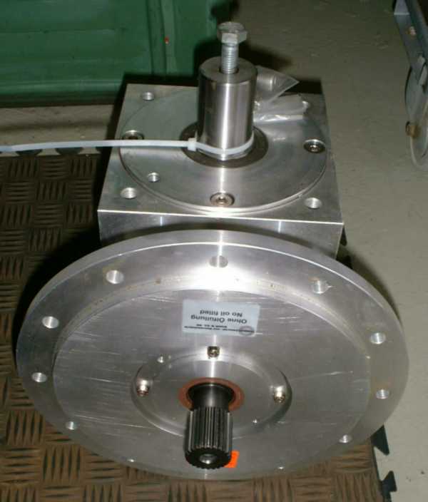 |
At this time we personally met for the first time and I showed him the governor hardware which was already finished for some months while I had not started the work on the software yet. We had some very enjoyable discussions about gearboxes, helicopters in general and a lot of turbine-related stuff. I also had the chance to show him a few of my engines.
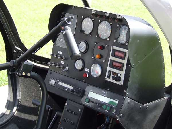
At that time the control panel was already more or less finished:
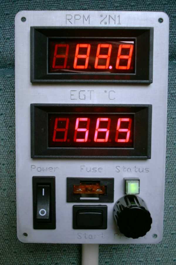 |
This photo has been taken during a dry test of the control panel and doesnt represent an actual engine condition.
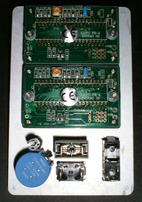 |
The panel mainly consists of two off-the-shelf LED panel meters for indicating RPM and EGT, a LED indicator for engine status, an RPM preset pot, a fuse (socket) to prevent fire in case of a short on the governor board, a toggle switch to activate main power to the engine systems and momentary switch to initiate the startup cycle. After this photo was taken, I machined another very simple PCB to provide a means to attach the control panel umbilical without having to directly solder to the components on the control panel. This allows for easier removal of the control panel and adjustment of the length of the umbilical.
Well, and then came early march this year when Platon invited me to come to Cyprus for late May / early June. Actually I still had not done a thing regarding the sequencer firmware (somehow I dont like this programming stuff, though once started, its quite fun to do it). Anyway, thats exactly the way that I get things done. One has to put just slight pressure on me and Ill actually do my job :-). So late April I finished the sequencer/protection software which turned out to be much less work than expected.
I decided to send most of the bulky and somehow airport-security-critical stuff in a parcel to Cyprus about three weeks before I would actually go there myself. This should leave me enough time to have another one of the governors ready in case the parcel wouldnt make it in time. Anyway, we were lucky and the parcel made it one week before I was supposed to arrive.
And then came that certain May 28th (Friday) when I stepped on the plane to Cyprus with hand luggage heavy as lead, containing a notebook computer, multimeter, clamp-on current probe, hand-held oscilloscope and programming equipment for Microchip PIC MCUs along with my digital camera and a camcorder. After a nice, calm flight I put my foot on Cyprus just before sunset and was welcomed very warmly by Platon and his lovely family.
This night we went out to the beach promenade of Larnaca where some kind of fairground-like festivity took place with a lot of music and folkloristic dances (I hope thats the right word... ;-). I also had the chance to have a look at the church where holy Lazarus has his grave. I can tell you Cyprus is a place where history of human culture meets the present. There are archeological sites on this island with artefacts dating back more than 9000 years. Really amazing!
Saturday: The next morning we picked up Platons friend Anthony and went to the hangar where Platons Ultrasport 496 and Anthonys Mini 500 helicopters are placed along with a decent amount of machining and tooling equipment. It is situated next to a beautiful small village called TOCHNI. It is told that this name has got its origin in the ancient Greek word Techni which is supposed to tell about the technical and artistic skills of the domestic stonemasons. Its quite a coincidence that Platon of course brings a huge amount of technical skills with him to this place!
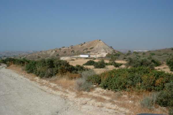 |
Thats the view from the road (well...sort of...) to the hangar. Its the white building just below the little mountain. The road is supposed to have tarmac put on early next year, so travelling there will become more comfortable then. Anyway, its a most lovely place where the hangar is located. Its very quiet so one can really concentrate on his work while he can make as much noise as he wants as well without disturbing anybody.
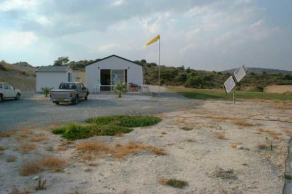 |
Directly in front of Platons hangar. Since the Hangar has got a large door in front and at the rear, the quite strong wind blows right through it and its very comfortable inside even if the temperatures may be quite high. At the left, theres a small kitchen and a lavatory so Platons got everything to stay there the whole day if he wants to. The self-tilting solar panel at the right (very clever construction...) supplies sufficient electricity to the facility so Platon actually hasnt got to start his diesel generator (placed behind the hangar) at all except for watering his plants.
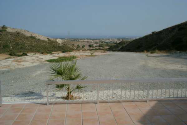 |
Isnt this a beutiful view from the porch in front of the hangar towards the Mediterranean?
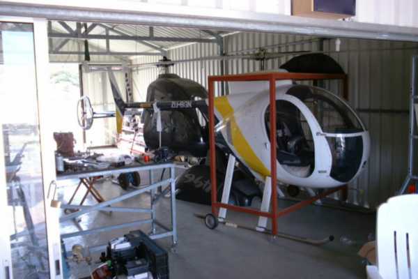 |
Inside the hangar, the two ultralight helicopters are placed on one side. The one in front is Anthonys Mini 500, a very cute looking craft. The one behind is Platons Ultrasport 496, maybe not as cute (sorry Platon ;-) as the Mini but much more versatile since it has got two seats and is probably mechanically a better design (dont know exactly since Im no helicopter expert, but with my limited mechanical experience it appeared to me like this - sorry Anthony ;-). Anyway, they both had been built with outstanding craftsmanship by Anthony who actually is an aircraft constructor by profession.
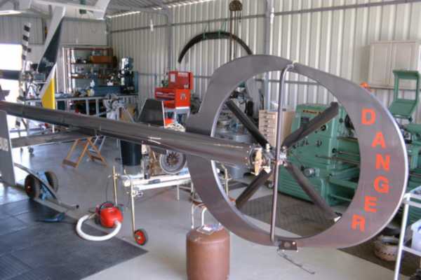 |
Thats a view from the other gate of the hangar. Actually work on the engine had already commenced when this photo was taken. But you can get an idea of how well equipped Platons hangar worshop is. He has got a small combined mill / lathe (but thats not supposed to be used in future anymore), a seven (!) axis tool grinding machine, a large lathe and a nice, big milling machine with digital measures attached. Moreover, he has got a very complete equipment of hand tools of only the highest quality. I was really impressed I have to admit.
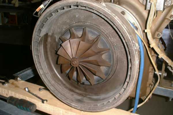
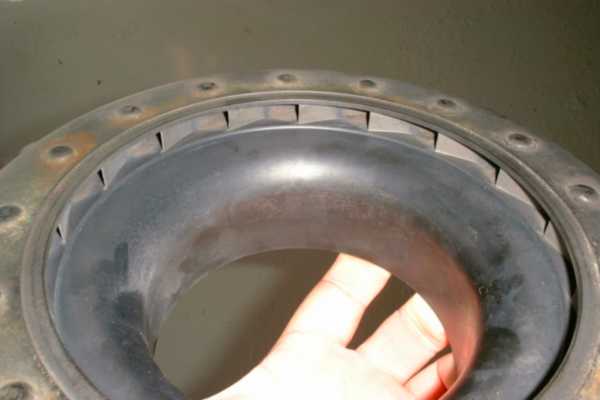
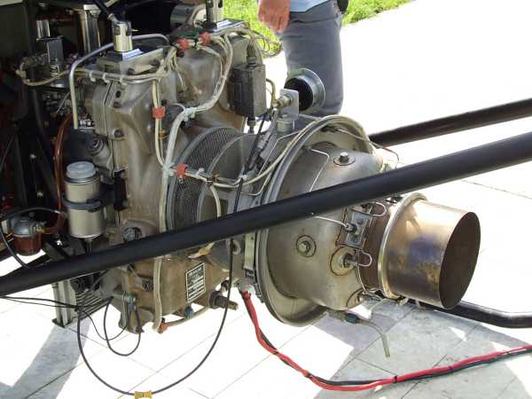
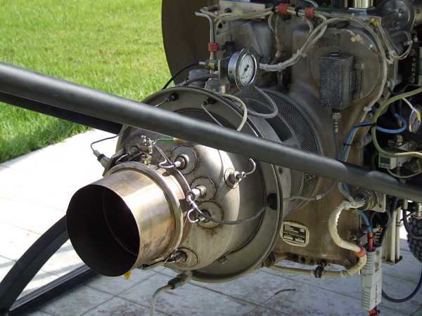
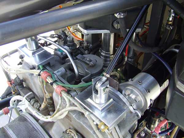
This day, we started with external inspection of the Solar T-62T-32 engine.
![]() Since the unit appeared to
be in a somewhat questionable condition with traces of storage under free sky or at least not in a completely moisture-fee environment, I suggested to have at least the hot section stripped down to make sure
everythings fine there and we wont have to expect a really dangerous experience. Since there was some minor corrosion on the external parts of the engine, I would have also liked to inspect the compressor wheel more
closely, but on engines with cantilevered rotor arrangements like the Garrett GTP30 or this Solar, this usually requires disassembly of the rotor shaft unit which is not without its problems since special tooling is required to
do so. Hence we just left it with a visible inspection of the compressor rotating inlet guide vane section thats visible from the outside.
Since the unit appeared to
be in a somewhat questionable condition with traces of storage under free sky or at least not in a completely moisture-fee environment, I suggested to have at least the hot section stripped down to make sure
everythings fine there and we wont have to expect a really dangerous experience. Since there was some minor corrosion on the external parts of the engine, I would have also liked to inspect the compressor wheel more
closely, but on engines with cantilevered rotor arrangements like the Garrett GTP30 or this Solar, this usually requires disassembly of the rotor shaft unit which is not without its problems since special tooling is required to
do so. Hence we just left it with a visible inspection of the compressor rotating inlet guide vane section thats visible from the outside.
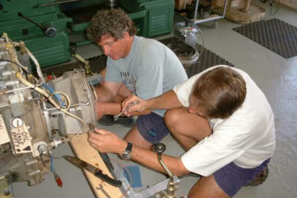 |
Platon (rear) and Anthony (front) are working at the engine. The combustor is already removed and they are about to unmount the NGV assembly.
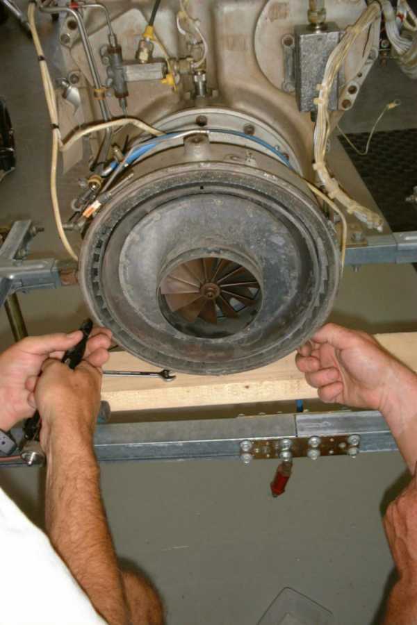 |
Some stains of moisture or even water appear to be present on the NGV and the rear parts of the compressor housing. Yet, apart from this, the hot section seems to be in a reasonably good condition.
 |
Finally the NGV is out. Theres some very minor surface corrosion on the rear compressor housing that can be wiped away with a damp cloth quite easily (already done at the lower half). The colour of the turbine wheel shows it has already run for some time but yet its still in perfect mechanical condition. There are no signs of heat damage as can be found on some of the T-62T-32 where the original electronic governor went bad.
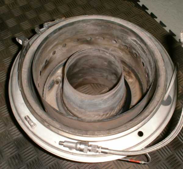 |
One quite interesting design detail of the T-62 is its combustor. Fuel is introduced through six airblast type fuel nozzles which probably also have some vaporizing capabilities. With this arrangement, the fuel injection pressure can be kept lower than it would be required in case of atomizing burners. Dilution air is applied only through a single row of holes in the outer combustor liner while both liners are cooled by a layer of cooling air, supplied by a row of small holes and an air deflection baffle on each side (inner and outer). As it seems, most of the primary combustion air is introduced through the airblast nozzles and a single row of small holes in the rear wall of the liner. This system only works correctly, if there is sufficient pressure differential across the combustor liner in order to atomize the fuel.
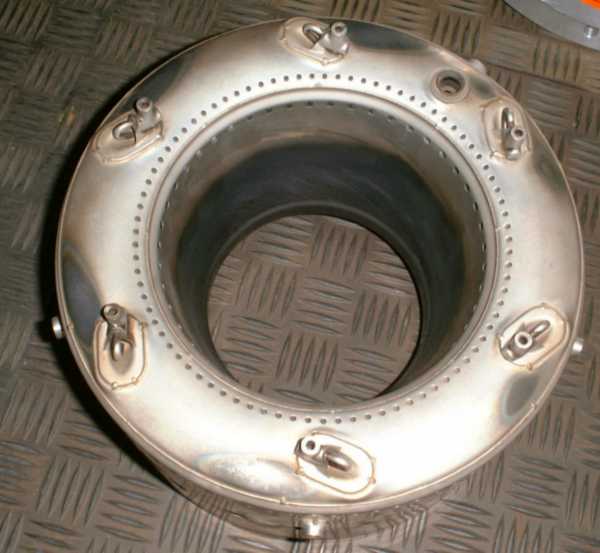 |
Here the combustor is shown from the rear. The hole in the 2 oclock position accepts the ignitor (spark plug) while the stub just visible at the outer liner allows the start fuel atomizing nozzle to project radially into the liner.
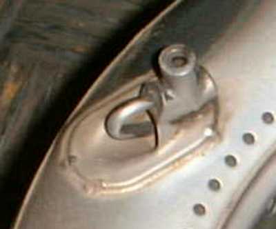 This photo is actually a
magnification from the above one, showing the arrangement of the airblast nozzle more clearly. The six fuel feed pipes project radially from the rear of the combustor casing and are inserted into the bores of the
transition pieces to be seen at the left. The fuel is guided by the transition piece into the U-bent tube which finally discharges it into the entry of the venturi duct. So these nozzles operating principle
is not much different from small but high fuel-flow carburettors. Yet I think, the radiated heat from the flame inside the combustor contributes to at least partial vaporisation of
the fuel. Anyway thats quite an interesting design detail Ive never seen on a turbine engine before.
This photo is actually a
magnification from the above one, showing the arrangement of the airblast nozzle more clearly. The six fuel feed pipes project radially from the rear of the combustor casing and are inserted into the bores of the
transition pieces to be seen at the left. The fuel is guided by the transition piece into the U-bent tube which finally discharges it into the entry of the venturi duct. So these nozzles operating principle
is not much different from small but high fuel-flow carburettors. Yet I think, the radiated heat from the flame inside the combustor contributes to at least partial vaporisation of
the fuel. Anyway thats quite an interesting design detail Ive never seen on a turbine engine before.
 |
The NGV assembly was discoloured but otherwise in very good condition. No cracks or traces of erosion were found so this part could be put back into the engine without any concerns.
While Anthony and Platon were cleaning the engine components, I started to figure out the electrical connection arrangement of the engines main umbilical connector. Since Platon had got both the socket (on some kind of control panel) and the plug (on the engine) together with the engine, I decided to use them to allow for a more comfortable way of attaching the governor to the engine.
We also found out that the thread that holds the compressor delivery probe fitting in place at the periphery of the compressor housing, was stripped. We discussed the options of holding the probe fitting in place with high strength putty or cement but we finally decided that only a metal reduction bushing would be up to the task permanently. So for the next day, machining of such a bushing was scheduled. Fortunately the hub that this fitting is supposed to be screwed in, provides enough meat to cut a larger thread as for the reduction bushing to be screwed in. I planned to finish the wiring of the engine the next day.
Sunday: This morning, Platon and me went alone to the hangar since Anthony had other duties. While Platon started machining the fitting as we discussed the previous day, I prepared a lot of wires to connect the umbilical socket to the plug that goes onto the governor unit. Since a lot of connections had to be made, the job took me almost the whole morning. At some time around noon Platon asked me to help him figuring out the right gear combination to be able to cut the external thread of the reduction bushing (we opted for a M14 x 1.5 since he had got the corresponding tap to cut the thread in the compressor housing). After some tampering, we finally sorted out the gears and Platon continued machining while I did some more electrical stuff on the engine (installing compensation wire for the type K thermocouple into the engines wiring harness).
Platon and me finished our work approximately at the same time and Platon proudly showed me his artwork. Actually, considering that it was the first time that Platon used a lathe to cut a thread, the result was not bad, but I tried to signal him as diplomatically as possible that the surface quality of the thread would probably not represent the craftsmanship usually to be found on a turbine engine. At least I wouldnt have used this reduction bushing if it was my turbine enigne... Of course it was a very nasty material to work with (hardened stainless), and maybe I should have told Platon a few tricks how a lathe-cut thread will turn out better. Since he cut the thread towards the chuck, he had to run the lathe quite slowly so he would be able to stop it soon enough before running into the chuck. Also, the cutting tool wasnt too sharp anymore. Since we still had a reasonable length of the base material left to have a second attempt, I re-ground the tool to shape and mounted it with the edge facing down so we could run the spindle of the lathe the other way round. This would allow us to cut the thread away from the chuck and we wont run into collision problems and could even run a higher cutting speed. Anyway, this collective effort was in the end rewarded with a reduction bushing that suited the application perfectly well.
After boring and tapping the hole in the compressor housing where the newly made part was supposed to go, we screwed it home with high-strength thread locking compound applied. This way it would never come out again and the mechanical arrangement would be better than new.
The last thing we did this afternoon was reassembling the engines hot section and putting the combustor housing back on using RTV sealant to get the system air-tight.
Monday: This day was the day we were supposed to start the engine for the first time. I wired everything up and wanted to do some dry tests, i.e. with a frequency generator instead of the RPM pickup and the engine actually spinning. Yet, it turned out the RPM and EGT signal readings at the control panel were quite unstable. After some tests with the oscilloscope it became very quickly clear that we had problems with switching noise superimposed to the floating supply voltage for the panelmeters. This was probably a result of the high supply voltage (27V) to the governor. Anyway, after some tweaking I got this problem sorted with four small capacitors placed at the inputs of the panelmeters and from their (floating) supply voltage terminals to ground.
Now that everything seemed to work just great, we decided to have an actual dry run on the starter motor. So all the required wiring was hooked up, the system one final time tested for a short, the power supply (four 12V lead-acid batteries of 200Ah each, wired in series/parallel which are Platons buffer of the solar panel electrical supply of the hangar) and I gave the Start button a firm push - chunk - and nothing else happened. So it appeared that the starter bendix engaged but the starter motor wouldnt run. Since Platon and Anthony stated that they ran it before with the power connected to the motors terminals directly, I assumed the problem could only be a bad starter contactor. Consequently we opened it and sure enough found what we expected.
A little touching up with fine sand paper made the contacts shiny again and after reassembly we were ready for the next attempt. Now, after pressing the start button, the engine picked up speed quickly and everything seemed to work about right. Since there was no oil in the engine yet, I immediately released the start button again as not to stress the engines bearings and gears more than necessary. So we filled in oil (five quarts) and were ready to go.
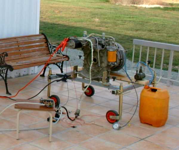 |
We placed the engine on the porch in front of the hangar, wired up the electrical low pressure fuel feed pump, added the fuel and finally were ready for the first real test. I must admit this was the first time I was quite excited and also a little afraid that something might go wrong.
And heres a video clip (1.6MB) of what that certain run was like. Actually, we had about everything of a real jet engine except ignition ;-). I cranked it for quite a while, yet only unburnt fuel mist was blown from the exhaust. After shutdown, the combustor housing drain valve opened and quite some fuel puddled beneath the engine. I was sure to hear the ignitor snapping but the others didnt, so we consequently removed it to check the presence of the spark visually. Fortunately, we had a spark and didnt have to bother about this. After a little reasoning why the engine might not have lit off, we agreed that it might have been due to the fact that the engine had been sitting for a long time and probably the fuel system was completely dry. So start burner fuel probably wasnt present soon enough to light, and later the airflow through the combustor might have been already too high to permit an ignition.
So we just gave it another try, shown here (1.4MB). This time we got ignition! When the engine accelerated happily, I had a look at the gauges and found we had an EGT reading of 0°C. Of course immediately I shut down the engine just short of 30% rpm to research this. Well, for sure it was my fault, I just placed the thermocouple compensation wires at the governor connector in reverse. So this problem was resolved within five minutes.
Now that we had got correct EGT readings, we had another start attempt. Actually we did two in sequence, and heres the clip (3.3MB). During both runs, the engine accelerated just up to 30% rpm and then flamed out. Since I pressed the main power switch too soon, I did not have the chance to check the reason for this behavior (i.e. condition of the status light on the control panel). Anthony suggested that we might have an oil pressure problem since the gauge just indicated zero after it came up during initial cranking for a split second. So we had the second start to find the same problem and sure enough, I got the error flashing from the status light. So probably the oil pressure switch didnt close the circuit and the security systems in my governor shut down the engine at 30% rpm after no oil pressure was sensed. As it later turned out, this function saved the engine (and possibly even more...).
We did a lot of testing this evening, trying to figure out the problem we had with the oil pressure. The pump would actually deliver a good flow of oil but with even the lowest flow resistance present, it would stop flowing. Platon was quite disappointed because we all expected to get the engine running this day. But since it was getting late already, we decided to separate the power section from the gearbox the next morning to check out whats wrong.
Tuesday: Once again we had nice warm weather (who would expect something different on Cyprus anyway?) and our mood was quite good again after the disappointing experiences of the last day. Immediately we started undoing all the wiring and plumbing to the power section of the engine and drained (most of) the oil from the gearbox. From the engines manual, we had a good understanding of how the lubrication system was supposed to work, and we suspected the pressure regulating valve being stuck open. Since this valve was located on the spider that holds the planetary gears, the power section had to be removed to gain access to it.
When we removed the power section, we found the pressure regulating valve to be located approximately at the 2 oclock position of the spider while it actually had to be exactly at the opposite place. Platon got a guilty smile on his face and we all started laughing. Platon and Anthony had to remove the power takeoff shaft when they were about to order the bevel gearbox and make it available to the gearbox manufacturing company so they could match the spline. Upon reassembly, Platon simply got the spider the wrong way in.
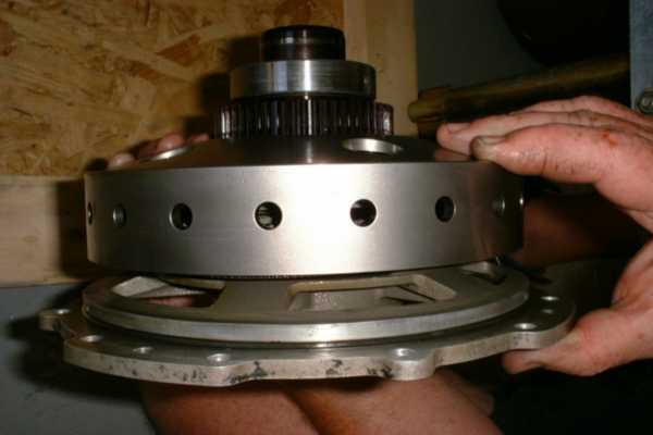
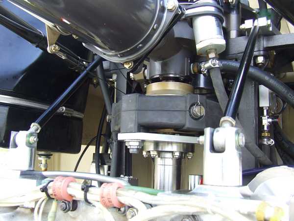
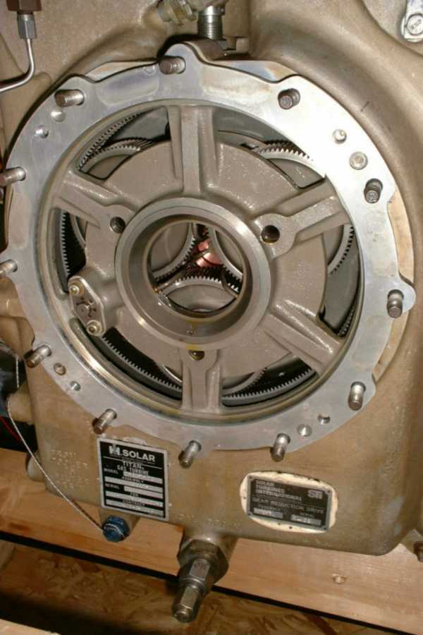 |
This photo shows the correct orientation of the gearbox spider with the oil pressure regulating valve located at the 8 oclock position. The hollow strut just lines with an orifice in the gearbox housing where the oil pump supplies its flow through the oil filter. If the spider is oriented the wrong way, this orifice is covered only about half-way so the oil just flows back to the sump. The bad thing about this is that theres no lubrication to the high-speed gears and bearings of the engine rotor. Yet, since we only had the engine up to 30% tree times in this condition, Im pretty sure no damage was done. At least the gears and bearings still had a thin film of oil on them.
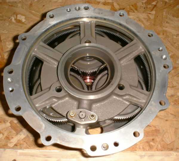 |
Here the spider is shown removed from the gearbox. The three small tubes running through the spaces between the planetary gears at about the centre of the spider supply oil to the intermeshing areas of the sun and planetary gears as well as via a small injection nozzle, to the high speed rotor bearings in the form of oil mist. This mist travels through a bore in the power section drive shaft, then turns around and goes through the rear bearing located inside the compressur hub. After that it continues through the shaft tunnel and the gearbox end (front) bearing of the rotor where it is being sucked out by an oil/air slinger. This way, a pressure differential is maintained all the time from the oil mist injection port to the front face of the gearbox end bearing of the high-speed shaft. Quite a clever design!
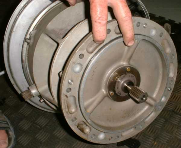
 |
Thats the spider viewed from the side. The holes in the side of the ring gear line up with the magnetic RPM pickup that works on the principle of magnetic reluctance. The gear just next to the bearing drives the accessories and is being driven by the starter motor upon startup.
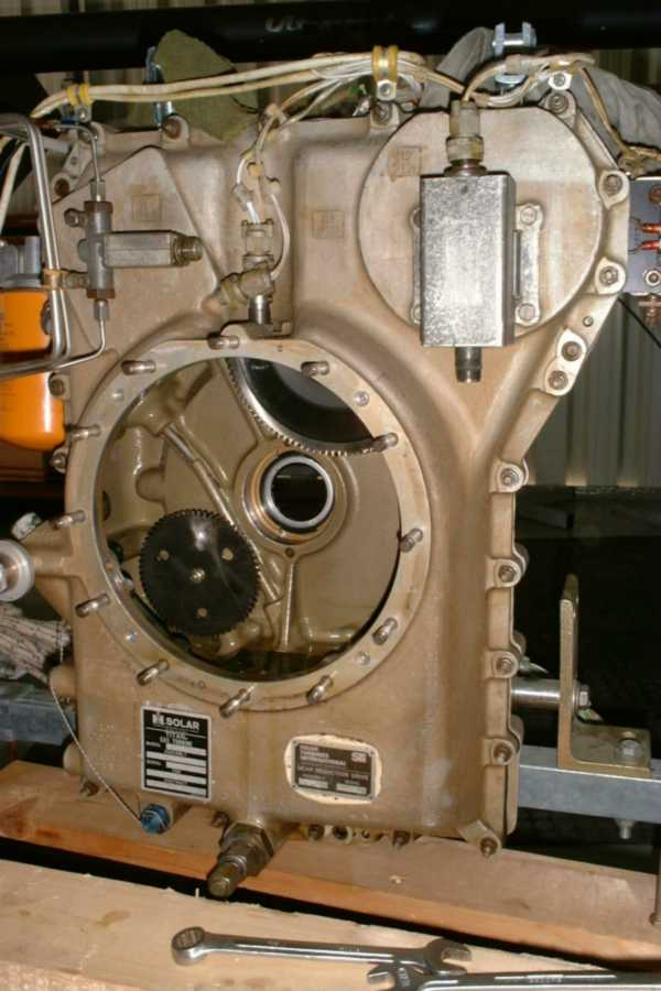 |
Here weve got another shot of the gearbox, this time with the spider removed. The lower gear drives the oil pump while the upper is a member of the auxiliary drivetrain.
 |
Here weve got the power section - well basically its mounting flange. The serrated part at the front actually isnt just a splined coupling but the sun gear of the planetary reduction gear system. It just centers all by itself between the three planetary gears. Just behind this gear, the oil/air slinger is located. The center bore in the gear/shaft assembly runs right into the hollow compressor hub to supply oil mist to the roller bearing loacted there.
Well, now that this problem was sorted and rectified, we were ready for more testing. Fortunately separating the main engine components can be done quite quickly and it took us a total of less than two hours to get everthing done. Now things started to get really exciting, and after a quick cold start to make sure we got oil pressure, we started it once more (1.6MB) with fuel and ignition on. This time, we quickly passed the 30% and the engine happily accelerated towards the 60% governor setting. At exactly that speed, the engine flamed out and gave a huge puff of smoke from the exhaust. I suspected the governor to close the fuel valve too quickly and consequently reduced the proportional gain a little bit (actually, derivative gain was adjusted to minimum during these first start attempts). So we were ready to have one more try and this time (success, success!!!) we got it governed for the first time (2.3MB). It just stayed rock-solid at 60% rpm. Anthony couldnt help but cry out in joy! Yet, we got some smoke from the exhaust so I assume that combustion isnt too good at this speed. This proved to be true when I started increasing the RPM preset a little bit and upon reducing the speed, we got another flameout. Later we actually found out, that with the start fuel nozzle activated and the restrictor in-line with the main burners, the Solar T-62T-32 is very likely to flame out if RPM is not reduced VERY carefully.
To further figure out the behavior of the engine / governor system, I still reduced the proportional gain and we started the unit again (1.7MB). This time I probably went too low with the gain and we actually got a runaway condition. As the engine headed for 80%, I quickly shut it down manually. The adjustment range of the pots on the TECM proved to be too large so I decided to replace them with others of smaller resistance to have a better control. Then I sat down for half an hour to do some calculations and a few educated guesses to do at least a preliminary adjustment of proportional and derivative settings as well as of the acceleration control and EGT limiting circuitry. Since the Solar is equipped with mechanical systems to adjust minimum and maximum flow (setscrews), I left my minimum flow pot at the lowest possible position.
During the next test runs, we had some hunting at governed speed so I did some further adjustments until we found quite a nice configuration. This time we already went up to 80% rpm (3.1MB) in small increments.
Now that we knew the engine was performing well with the governor (at least so far), Platon phoned his family and they came over to the hangar quite quickly.
With them present, we had another run up to 80% (actually I felt a little uncomfortable since running a turbine engine of more or less unknown history isnt the safest occupation one can imagine). Anyway, everything worked just well and Platon wanted his dad (just right behing the engine in this clip, 4.3MB) to start the turbine - and he finally did it, making Platon very happy.
I didnt push the speed of the engine any further up while Platons family was present due to safety reasons. To be honest, I was quite scared to go beyond the 96% point when the start fuel valve will cut out and bypass the restriction to the main fuel nozzles. Anyway, it had to be done and finally I got a heart and just did it. Once again we got a little hunting but it stabilised all by itself. What a blast I can tell you! To check combustion stability, I gave the engine quick acceleration/deceleration adjustments in the range of 95-100%. No combustion problems were observed and the engine had very fast throttle response. This certain run (4.4MB) was actually the first one that wasnt terminated by a flamout or another problem but by me pressing the shutdown switch.
We did quite some more testing and also a few more adjustments in order to do away with the short, minor hunting at 100% rpm and also found out that throttling from 100% down to 60% in one quick flip of the RPM preset was possible without flamout since once the start fuel valve is disengaged, it stays this way and leaves the restrictor to the main fuel nozzles bypassed. Anyway, at 60% weve got some smoke from the engine as well as during startup and after shutdown. I partly blame this to the fuel we used - low sulphur diesel and not kerosene. But what the heck, the engine works just great at around 100% and I think a load will rather stabilise its operation since its reaction will become slower. But thats one thing that has to be found out later.
On Wednesday and Thursday I did some tweaking of the safety features in the governors microcode to meet the requirements of an application in a helicopter (first save the pilots life, then the engines ;-). I also helped Platon with some electrical stuff in his workshop and then we went off and Platon showed me some nice places of the island during the other half of these days.
 |
For instance, thats the place where - as told by ancient Greek mythology - Aphrodite, the Godess of Love, was born. Actually this photo doesnt do justice to the real place - it was so amazing to see the huge cliffs sloping steeply down to the Mediterranean. A strong, warm wind was blowing towards the shore and color of the water probably cannot be reproduced in any photo. I was really sad I had to leave Cyprus the next day but anyway, Im sure Ill come back again one day in future.
Now that Platon has got a running turbine engine, I guess the real work is just about to begin. It will still take a lot of effort to actually put it into the helicopter and get everything rigged up.
I really want to thank Platon and his wife Maria for giving me such an amazing time on Cyprus, and of course for the great meals Maria prepared for us. Thank you so much!
Btw, currently Im considering to offer my governor/sequencer units for sale especially for use with the Solar T-62T-32 engines. Production will still take some time since many different suppliers of componets will be involved, and as yet I havent even decided for a price of this unit. But if anyone is interested in one of these devices, please just drop me a line. Contact. And if anyone has got a spare T-62T-32 engine he or she wont need anymore, I would be very much interested in a deal or partial trade if it is available at reasonable expense. It wouldnt need to be in mint condition but it should be mechanically sound and in (more or less) operational shape.
11/08/2006
Meanwhile more than two years have passed and both Platon and me had been quite busy. We
met four times since, twice he came to Germany and Ive been to Cyprus two more times as well. Unfortunately my visit in march this year wasnt that successful - I intended to adapt a nice
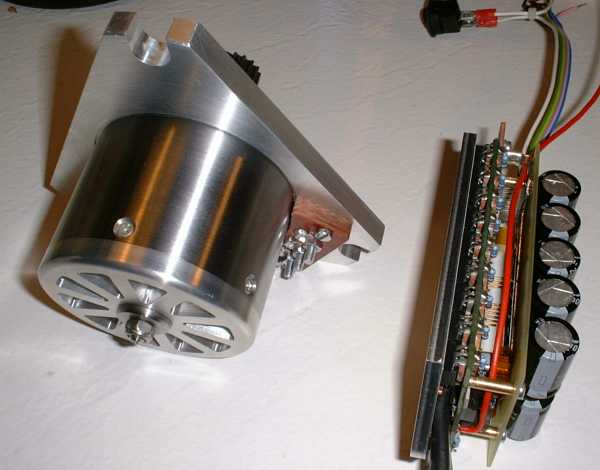
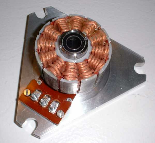
brushless starter generator to Platons engine that I designed specifically for this application. It was of the brushless, sensorless outrunner design (LRK). It would have meen more than powerful
enough to crank the engine. Yet the inertia of the turbine rotor driven by the gearbox during startup, combined with the considerable friction caused by the fuel and oil pump systems made
it impossible to get the transition from forced motion to back-EMF feedback motion in the electronic motor controller right. This means, it was impossible to make the motor running
continuously and accelerating smoothly. It might have been possible but Im not the real software guru even I get along fine usualyl with my programming jobs. Anyway, I guess a brushless motor
with position sensors would have been the way to go. Thats what our system looked like:
 |
 |
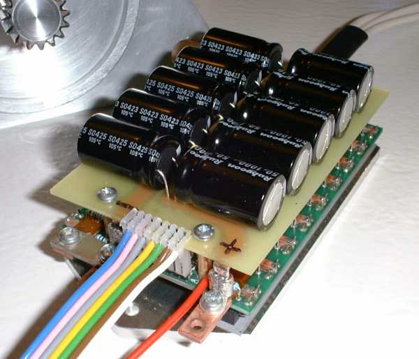 |
This last photo show my really sophisticated brushless sensorless motor controller that should be capable of approx. 400 Amps. Well, I never really tested it...call me a coward ;-)
Anyway, Platon got the starting problem sorted by himself. Firstly he used a Plettenberg Dino which worked fine until he attempted a startup cycle with the clutch (and consequently main rotor) engaged... This caused the motor to release its magic smoke. After that he found a Magmotor that produces truely amazing power and doesnt even seem to get warm during startup of the engine. Now the engine reaches 40% idle in less then ten seconds after pressing the start engine button.
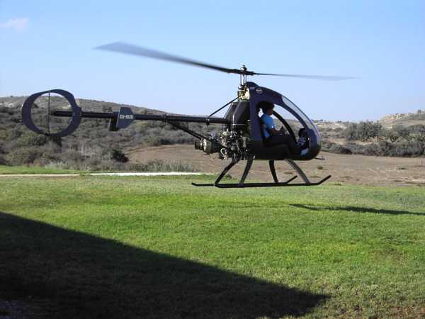
With this system and a complete installation of the engine, Platon actually did several hover flights with his Turbine Ultrasport 496 (a total of about 16 hours if I remember correctly), assisted by our friend Keith KGB Baker from Australia. Yet, he found several small annoyances and he had a few almosts although since he never flew any higher than perhaps two meters, a real problem wouldnt have damaged anything other than his helicopter and probably his pride.
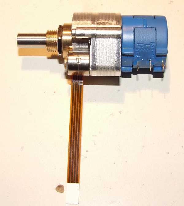
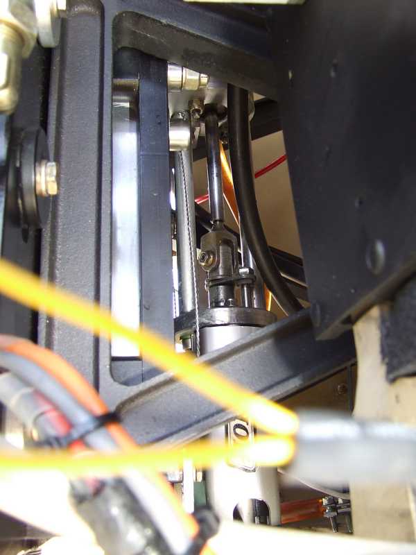
Yet, these small difficulties caused Platon to ask me for some assistance again. Since he isnt able to reach the panel once hes got his seatbelts on, he definitely needed a means to trim engine RPM as well as initiate an emergency shutdown. Moreover, it would be very convenient to have a system that automatically engages the clutch after the engine has reached approx. 65% RPM and produces enough power to crank up the rotor. Also, the RPM preset pot I put on the original engine control panel was way too coarse (just a 270° type). So I desigend and constructed a tiny motor pot since something like this isnt commercially available yet. Its a ten turn (3600°) wire-wound precision pot equipped with a truely tiny stepper motor:
 |
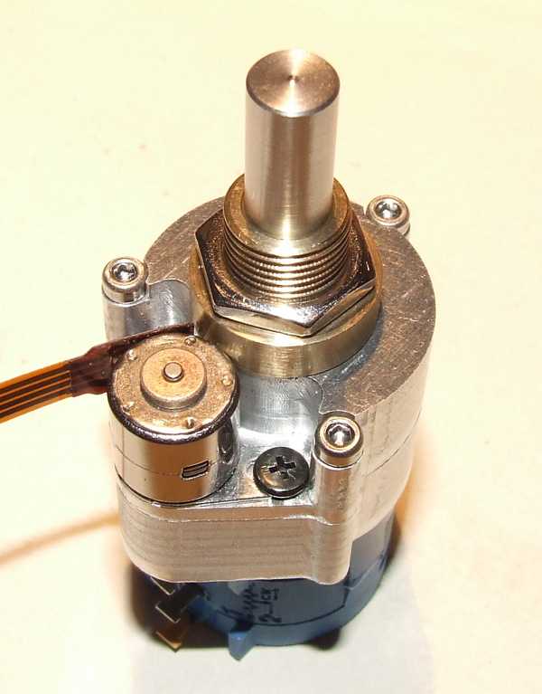 |
This pot is controlled by a small electronic board that drives the stepper motor and converts the trim switch input to the appropriate movement. After long reasoning, we decided to include a wind-down after switching on the whole system. This means, the pilot cannot forget to reduce preset RPM to idle. I was a little afraid of what might happen if theres a momentary loss of electrical power. But this would stop the engine anyway since the governor is also affected. The switch input pwemits a motion of one turn at a time. This means, to go from idle to full power, you have to push the RPM trim switch at least ten times up. I arranged the control this way because this would cause the RPM to change at maximum by 6% if theres a short in the wiring somewhere. Yet, by pressing the trim switch for shorter times than whats required for a full turn, the RPM can be adjusted by arbitrary amounts. Platon was very happy with this arrangement even though mounting the pot directly at the cyclic stick might have done the trick as well...
 |
I also did some re-programming of the engine sequencer device to do away with the automatic shutdown in case of a serious engine problem. This includes high EGT, low oil pressure and slight overspeed. These would have caused a shutdown of the engine before. Now we placed a devils eye warning light on the panel (the red one above the yellow light) that signals the serious problem to the pilot. Since it is well possible that theres a fault in a pressure switch or another place of the system, and the engine might even continue to work for considerable time with low oil pressure or too high EGT, shutting down the engine is up to the pilot so hes got at least a little more time on power to land the helicopter. Yet, a serious overspeed is always a reason for a shutdown because the result of such a situation will be more critical than a forced autorotation.
We also implemented a kill switch thats located at the collective stick. The switch itself ist equipped with a mechanical lock so it cannot be pressed accidentially. I also implemented an electronic safety system that requires the switch to be pressed at least for half a second to shut down the engine. This eliminates the effect of electrical interference. The kill switch doubles as a cold crank initiator. If it is pressed directly after switching on the engine systems, it will cause a cold crank cycle when the engine start button is pressed. This is also signaled to the pilot by the engine status light.
Next combined effort will be designing a new panel with displays that are more easily readable in bright light as well as constructing a new, less chaotic wiring loom. Since several other Ultrasport 496 are supposed to be converted to turbine, this will be mandatory for future installations. Ill contribute to the panel design. Moreover, I decided to make a new PCB for the engine control system. I simply want to have the connections for the engine, panel and other system components located on separate connectors so wiring everything up will become a lot easier. Moreover, the new system will be a single PCB design (no piggyback as the current one) thats protected in a layer of polyurethane resin. This will also permit operation of the sytem in the rain. The current configuration can still be considered a prototype with the correcponding shortcomings. I might also include an H-bridge output stage to control the toque motor that controls fuel flow to the engine. This would cause the system to become independent of the return spring at the torque motor lever. Anyway, this would mean a lot of testing on an engine will be required. Yet, this wouldnt be a problem anymore since Platon and me bought three T-62T-32 engines of which two will need substantial repair work. Anyway, thats something Im quite experienced at. Have a look here for some more details if you please.
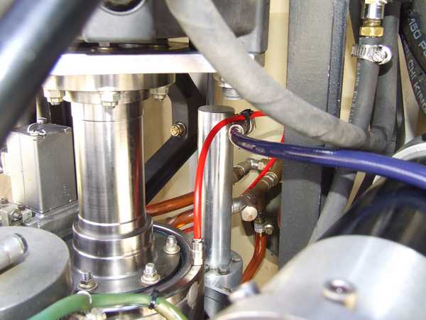
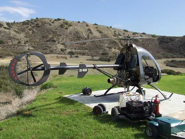
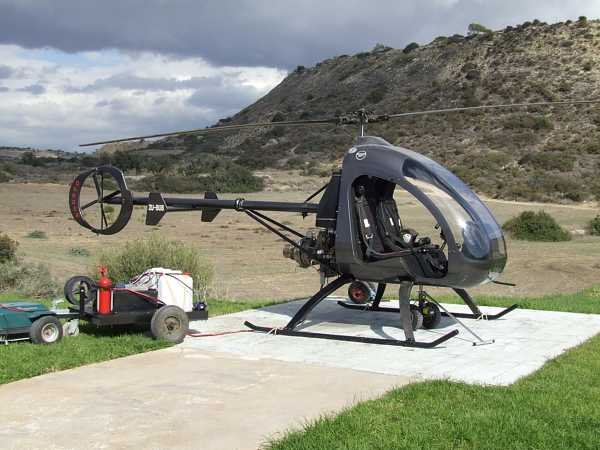
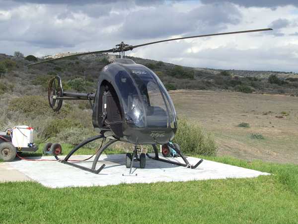
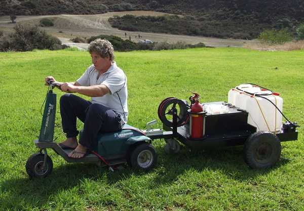
Now several photos show Platons Ultrasport 496 and how he arranged things. I especially like his starting cart!
 |
 |
 |
 |
 |
 |
 |
 |
 |
 |
 |
 |
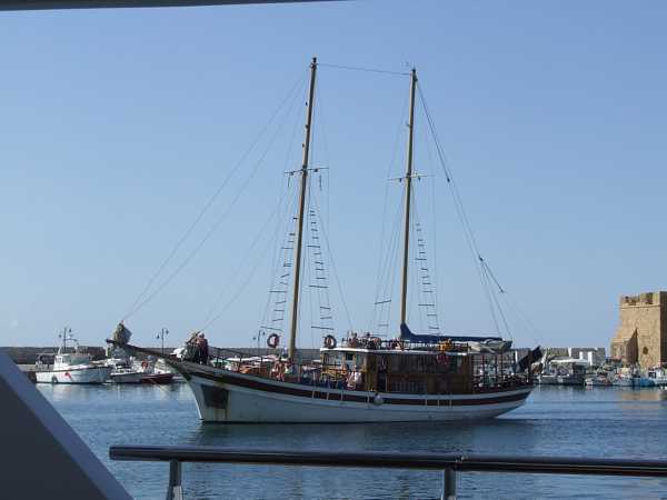
Since we were very busy doing the extensitions and modifiactaions, there was only little time left for relaxing. Yet, on Sunday we had the chance to do a trip on a true luxury yacht... Look at this:
 |
 |
Aboard the yacht, Maria and Platon. Thanks for all your patience with me and the very warm welcome!
 |
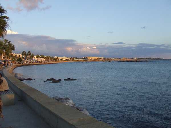 |
Two more photos of Paphos harbour and the beach promenade...beautyful!
 |
From left to right: Me, Platon and Marios, another helicopter homebuilder and also the guy who arranged the trip on the yacht for us. Thank you, Marios, this was a great experience!
And for those of you who still havent got enough, heres a short video clip of a tethered run of Platons helicopter (10MB).