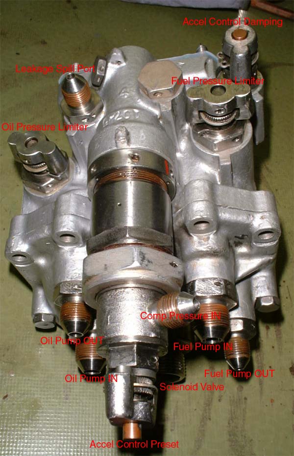
On this page you will find pictures taken during disassembly of the fuel control unit (FCU - sounds better than pump). Integrated in one common housing are two gear pumps, driven at different speeds by a single electric motor. Along with these pumps there are at least two adjustable pressure release valves, one adjustable metering valve, one adjustable, pneumatic pressure differential operated control valve, one solenoid valve and three screen filters. Theres quite some difficult web of bores in the FCU block that guide the different fluids to where they are needed.
 |
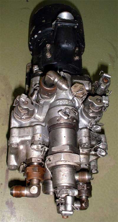 The FCU has a total of six pipe
fittings, four adjustment screws and two ambient air pressure balance ports. The motor is very powerful, its a four-pole machine with an electromagnetic field winding. A quick test with a power supply
capable of 25A current showed that the motor will need 10A to start turning, so I guess at 28V it will consume at least 50A to operate the two pumps. Hell of a powerful device.
The FCU has a total of six pipe
fittings, four adjustment screws and two ambient air pressure balance ports. The motor is very powerful, its a four-pole machine with an electromagnetic field winding. A quick test with a power supply
capable of 25A current showed that the motor will need 10A to start turning, so I guess at 28V it will consume at least 50A to operate the two pumps. Hell of a powerful device.
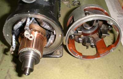
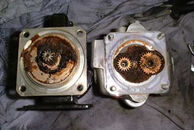 Heres the motor (left) removed from
the pump housing. The smaller of the two gears drives the fuel pump while the larger one drives the oil pump (at least thats what Ive figured out so far, but I might also be wrong). Theres a lot of hardened, nasty
grease in the cavity of this small gearbox that will need to be removed completely. Theres also some oil on the commutator of the pump motor, so this must be disassembled as well. I hoped I could avoid this (lots
carbon dust with oil sludge, gloves will be mandatory), but who would complain?
Heres the motor (left) removed from
the pump housing. The smaller of the two gears drives the fuel pump while the larger one drives the oil pump (at least thats what Ive figured out so far, but I might also be wrong). Theres a lot of hardened, nasty
grease in the cavity of this small gearbox that will need to be removed completely. Theres also some oil on the commutator of the pump motor, so this must be disassembled as well. I hoped I could avoid this (lots
carbon dust with oil sludge, gloves will be mandatory), but who would complain?
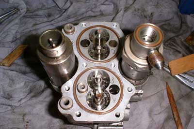
 Finally the pump cover is removed
and the gear pump axial spacers (brass) are visible.
Finally the pump cover is removed
and the gear pump axial spacers (brass) are visible.
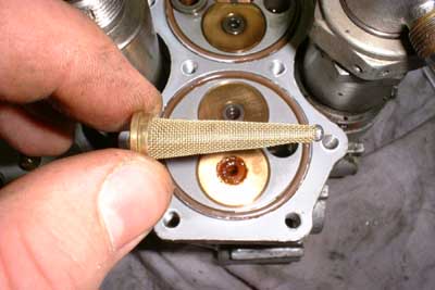 Heres one of the filters. It is soldered
from wire mesh to a beautiful cone shape. Both filters are located in bores of the pump housing. Notice the rust in the lower pump spacer/bearing. Some water must have been entrapped there that
caused the shaft material to rust. I hope no damage has been done to the journal bearing surfaces.
Heres one of the filters. It is soldered
from wire mesh to a beautiful cone shape. Both filters are located in bores of the pump housing. Notice the rust in the lower pump spacer/bearing. Some water must have been entrapped there that
caused the shaft material to rust. I hope no damage has been done to the journal bearing surfaces.
 The pump spacers are pulled. For
correct reassembly I numbered the four spacers and the corresponding locations. The gears have M3 threads in them so screws can be inserted to pull them out. Yet it must be considered that both gears of
each pump must be pulled simultanously or the spacers will lock each other. Still the four M3 screws are inserted in the center of the four gear shafts.
The pump spacers are pulled. For
correct reassembly I numbered the four spacers and the corresponding locations. The gears have M3 threads in them so screws can be inserted to pull them out. Yet it must be considered that both gears of
each pump must be pulled simultanously or the spacers will lock each other. Still the four M3 screws are inserted in the center of the four gear shafts.
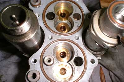 The gears are removed as well.
There are brass inserts in the casting, yet I dont know if they are pressed in or if they had been included prior to casting the housing. Inside the bearings that open to the gear box side there are shaft
gaskets that prevent leakage of oil or fuel to the gear box side of the pumps.
The gears are removed as well.
There are brass inserts in the casting, yet I dont know if they are pressed in or if they had been included prior to casting the housing. Inside the bearings that open to the gear box side there are shaft
gaskets that prevent leakage of oil or fuel to the gear box side of the pumps.
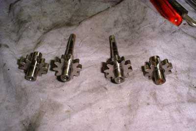 Finally a shot of the gears. They look
almost mint (except for the little rust on one of them). There are no traces of wear so this pump cannot have been in operation for a long time. Fortunately the bearing surface of the rusted gear shaft isnt damaged. So
Ill just try to remove the existing rust and then lubricate and reassemble the pump. But not before Ive figured out how all the bores and valves operate together and Ive completely understood how acceleration control
and governor operate. And that will be next on my list.
Finally a shot of the gears. They look
almost mint (except for the little rust on one of them). There are no traces of wear so this pump cannot have been in operation for a long time. Fortunately the bearing surface of the rusted gear shaft isnt damaged. So
Ill just try to remove the existing rust and then lubricate and reassemble the pump. But not before Ive figured out how all the bores and valves operate together and Ive completely understood how acceleration control
and governor operate. And that will be next on my list.
 Ok, work commences! Here I
removed the solenoid located at one side of the FCU. Its plunger is pushed outwards via a spring. When the solenoid is energised then the punger is pulled back against the spring force. The front end of the
plunger contains a polished metal plate with a ball behind (not visible) so that the plate will adjust its angle within a limited range to a surface it is pushed onto. On the left there is
this surface in the shape of an orifice that is ground flat.
Ok, work commences! Here I
removed the solenoid located at one side of the FCU. Its plunger is pushed outwards via a spring. When the solenoid is energised then the punger is pulled back against the spring force. The front end of the
plunger contains a polished metal plate with a ball behind (not visible) so that the plate will adjust its angle within a limited range to a surface it is pushed onto. On the left there is
this surface in the shape of an orifice that is ground flat.
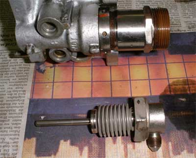 Here the acceleration control is
disassembled further. The lower part of this picture shows a stainless steel bellows that is pressurised with compressor air from the inside. The fitting with the ring nut in the upper part contains the air and fuel seals
and the vent to the atmosphere and contains the bellows below.
Here the acceleration control is
disassembled further. The lower part of this picture shows a stainless steel bellows that is pressurised with compressor air from the inside. The fitting with the ring nut in the upper part contains the air and fuel seals
and the vent to the atmosphere and contains the bellows below.
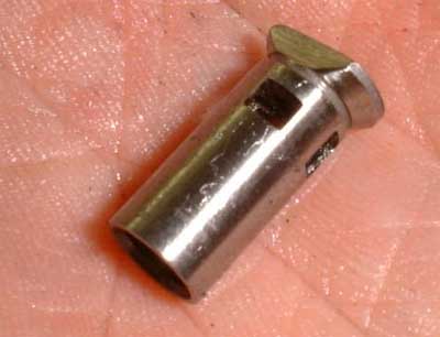 Thats one of the smaller but rather
important components of the acceleration control unit. Its about 10mm long and is the moving part of a piston valve. This piston is located inside of a precisely fitting cylinder so that the orifices on top of it are
covered. Fuel pressure is applied at the bottom (the open end). As long as the force onto the top face of this piston is larger than the force exerted by the pressurised fuel in the opposite direction, the valve will stay
closed. If the fuel pressure increases, the piston will eventually move outward and push the orifices out of the cylinder, thus spilling fuel to reduce pressure.
Thats one of the smaller but rather
important components of the acceleration control unit. Its about 10mm long and is the moving part of a piston valve. This piston is located inside of a precisely fitting cylinder so that the orifices on top of it are
covered. Fuel pressure is applied at the bottom (the open end). As long as the force onto the top face of this piston is larger than the force exerted by the pressurised fuel in the opposite direction, the valve will stay
closed. If the fuel pressure increases, the piston will eventually move outward and push the orifices out of the cylinder, thus spilling fuel to reduce pressure.
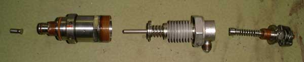
An thats the arrangement of the components of the acceleration control. From left to right there are piston valve (corresponding cylinder located permanently in the FCU housing), sealing tube with vent to the atmosphere, bellows with spring and plunger, the fitting accepts compressor pressure, and finally the preset spring with adjusting knob. This differential pressure valve works such that compressor pressure will push the plunger to the left, thus increasing the force to the piston valve. So with an increasing gas generator speed the fuel pressure will be increased as well. This is necessary to prevent the engine from being overfuelled (hot start) and keep the turbine and NGV temperatures within permitted limits. The two springs with the adjustment knob allow biasing of this valve to match the pressure range with the requirements.
Finally I figured out how the whole fuel control unit works. One of the gear pumps (the one with the lower operating speed) is the oil pump. It is bypassed by the adjustable pressure relieve valve with the softer spring to prevent hydrolocking the pump in case of a too low oil flow (possibly as a consequence of low temperatures and high viscosity). The other gear pump (which almost turns twice as fast as the oil pump) is the fuel pump. This one is bypassed by the second pressure relieve valve (the one with the stronger spring), its also bypassed by the solenoid valve, so the fuel pressure will be reduced to almost zero if the solenoid is fully energised. It may well be possible that an RPM adjustment within a limited range is possibly by applying less than full current to the solenoid (or pulse-width modulating it), thus reducing the effective force that pushes the sealing plate onto the spill orifice. The fuel pump has a third bypass that consists of the piston valve that has the metering valve in series at the high-pressure side. This metering valve is probably located there in order to impose a resistance to the fuel flow to prevent the acceleration control system form going into oscillation. Adjusting this valve correctly might be one of the more difficult (and dangerous) tasks to be accomplished. The pressure relieve valve at the fuel pump probably acts as a primitive governor for the engine as it simply limits the maximum fuel pressure to the combustor. But as viscosity of the fuel changes with temperature, the fuel flow will also increase once the engine is heated up. Theres a fifth connection port at the body of the FCU that ducts fuel and oil that got past the gaskets of this unit overboard.
Next will be disassembly of the FCU drive motor to remove the oil from the commutator and the carbon brushes, then cleaning of all the components and reassembly. During this Ill probably take some more pictures.
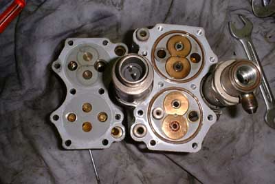
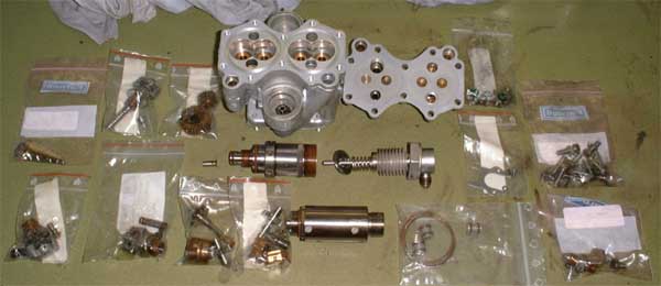
Today I got all the FCU components cleaned. Below all components less the motor are shown, neatly arranged in groups and packaged in plastic bags to simplify reassembly. Theres quite some stuff in this unit, in components count it may reach the turbine itself.
Below the almost completely reassembled FCU is displayed, yet still missing the motor. Everythings clean again and the ports and adjustment screws are explained. Though the unit seemed to be rather complicated at the first view, it turned out to be of quite simple, reliable design. Though I cleaned everything thoroughly, I will probably run a few liters of oil and kerosine through it to purge out all possible remaining dirt before I hook it up to the engine
 Heres the FCU motor opened. I had
to remove the commutator bearing retainer to get access to the commutator which was covered with an oily sludge of carbon dust. After cleaning it turned out that the commutator wasnt actually smooth
but looked as if it had been ground with a rather rough grinding stone. So I used a rubber file, a piece of soft rubber-like plastics with fine abrasives immersed in the material, to rework the commutator. This gives
an nearly polished appearance. The carbon brushes are currently drowned in white spirit to solve the soaked oil out of them. I hope to get them clean enough to
be re-usable because it might be quite difficult to find suitable brushes for this motor.
Heres the FCU motor opened. I had
to remove the commutator bearing retainer to get access to the commutator which was covered with an oily sludge of carbon dust. After cleaning it turned out that the commutator wasnt actually smooth
but looked as if it had been ground with a rather rough grinding stone. So I used a rubber file, a piece of soft rubber-like plastics with fine abrasives immersed in the material, to rework the commutator. This gives
an nearly polished appearance. The carbon brushes are currently drowned in white spirit to solve the soaked oil out of them. I hope to get them clean enough to
be re-usable because it might be quite difficult to find suitable brushes for this motor.
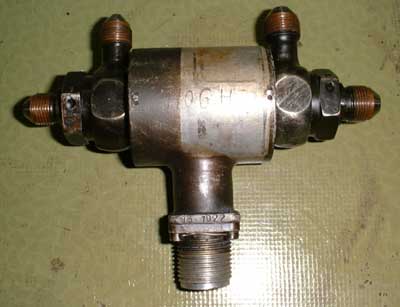 Thats not a part of the FCU itself but
I put it here because it is a part of the fuel/oil system. It is a two way solenoid valve, opening or closing two separate flow paths simultaneously with a single solenoid. This is probably used to
disconnect the APU from the main engine fuel/oil system when the APU is not in use. Maybe its also some kind of emergency shut down valve. Yet Ill have to figure out where it exactly goes.
Thats not a part of the FCU itself but
I put it here because it is a part of the fuel/oil system. It is a two way solenoid valve, opening or closing two separate flow paths simultaneously with a single solenoid. This is probably used to
disconnect the APU from the main engine fuel/oil system when the APU is not in use. Maybe its also some kind of emergency shut down valve. Yet Ill have to figure out where it exactly goes.
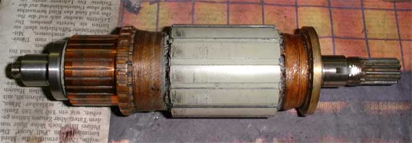
After some testing of the motor it turned out that the bearings arent in too good condition anymore. There was some radial play (less than 1/10mm) but the motor was vibrating and noisy as well. So today I removed the rotor to replace both bearings with new, sealed ISO6202 types. Upon disassembly it turned out that the old bearings are of different width than the ISO ones, namely 14mm instead of 11mm. So Ill have to make some bushings as spacers to firmly seat the new bearings. The picture below shows the rotor of the FCU motor. From the general construction it becomes clear that this rotor is designed for high speeds (thread-epoxy reinforced windings, balancing washer on the right) and for short-term use, considering the aspect ratio of commutator and rotor armature.
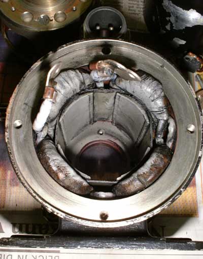 This is the stator armature of the
FCU motor. As easily to be seen it is a four-pole machine. The two terminals at the 12 oclock oposition are from the two armature coils, the other terminals of the armature are internally connected to one pin of the
socket on top. The terminal at the 9 oclock position is directly connected to the other pin of the socket. These terminals are connected to the brush holder located in the bearing shield.
This is the stator armature of the
FCU motor. As easily to be seen it is a four-pole machine. The two terminals at the 12 oclock oposition are from the two armature coils, the other terminals of the armature are internally connected to one pin of the
socket on top. The terminal at the 9 oclock position is directly connected to the other pin of the socket. These terminals are connected to the brush holder located in the bearing shield.
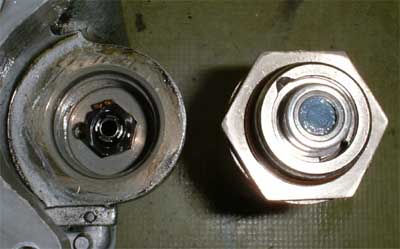
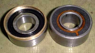 Here are the bearings shown. On the
left theres one of the new bearings with rubber gaskets and a brass spacer ring on top to match the width of the original bearing, as shown on the right side. The reinforced phenolic resin gaskets of these old
bearings have degraded with the time and most of the grease has been washed out. Also carbon dust from the brushes found its way into the bearings, causing rough running. After preliminary assembly of the
new bearings I powered the motor up and found it to run much better. Theres almost no vibration left and the operating noise is also much lower, especially if the cummutator shielding cup is in
place. I will also have to replace the bearings of the two pump drive shafts, but hopefully they will be standard ISO types so that I wont need to make spacial parts. With these replacements the
FCU will hopefully be up to the task to test the engine at least.
Here are the bearings shown. On the
left theres one of the new bearings with rubber gaskets and a brass spacer ring on top to match the width of the original bearing, as shown on the right side. The reinforced phenolic resin gaskets of these old
bearings have degraded with the time and most of the grease has been washed out. Also carbon dust from the brushes found its way into the bearings, causing rough running. After preliminary assembly of the
new bearings I powered the motor up and found it to run much better. Theres almost no vibration left and the operating noise is also much lower, especially if the cummutator shielding cup is in
place. I will also have to replace the bearings of the two pump drive shafts, but hopefully they will be standard ISO types so that I wont need to make spacial parts. With these replacements the
FCU will hopefully be up to the task to test the engine at least.
To be continued.