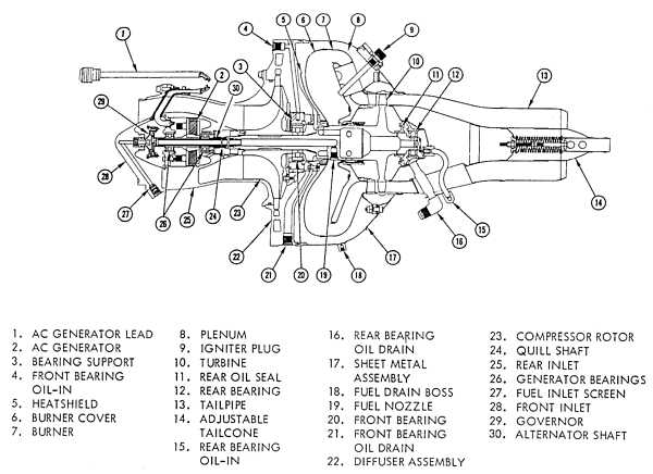
Williams Research WR2-6
or my own private Scrapheap Challenge
In late june this year (2004) I noticed a badly damaged Williams Research drone turbojet engine on german eBay. I decided to let the auction pass since I assumed it would go quite high and I have enough unfinished toys in my playground anyway. Well, finally a fellow turbine collector with whom Ive been in touch for several years but who Ive met in person only once (his names Peter), won the auction. He phoned me and asked for my opinion about the engine. He also explained that the seller still has got several of these units and that he already bought another one from him. As it finally turned out, the seller still had nine WR2-6 of which three were already reserved for other people. So we quickly decided to buy the remaining six engines as a bundle at a very competitive price.
Peter beforehand partially disassembled his two engines and told me that except for the combustor casing and the thrust nozzle, the engines appeared to be undamaged. The seller blamed the damage to careless handling of the drones at the place where he picked them up (must have been some kind of scrap yard) but to me it rather appears to be the result of landing damage of the drones, probably due to a failure of the airbags that are supposed to soften the impact.
The WR2-6 is a very early design of Williams Research Company (early to mid nineteensixties) which eventually led to their similar, but more sophisticated WR24 series. Today Williams International designs and produces small turbofan engines both for drones and for general aviation, offering some of the smallest fan engines available on the market today (FJ22 and FJ33). The WR2-6 was manufactured for Canadair for use in their CL-89 reconnaissance drone which was introduced in the german military during the early ninteenseventies.
 |
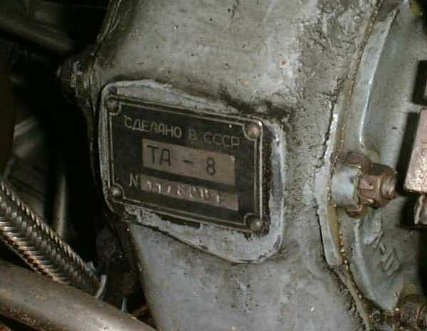
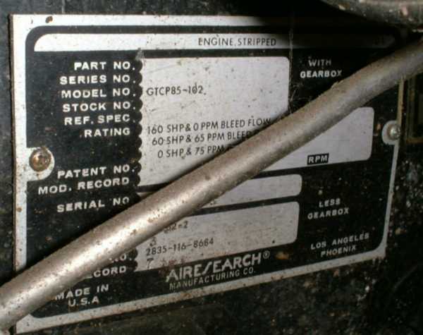
Now this way, three of these impact-damaged engines found their way into my shed. Actually yesterday, when I picked up the engines, was quite remarkable since this was the first time that I visited Peter at his place. Hes got a time-expired Alouette II helicopter, several military trucks and towing vehicles, an amphibious car, a small caterpillar and other devices I cannot even describe. Better meeting my own collection favorites, he has got two TS-21 jet fuel starters, a GTD-350 (helicopter engine of the Mi-2), a GTCP85-102 (dont know where this APU was originally used) and a Russian-made TA-8 APU which he has in more or (rather) less running order... Please click here to go to the bottom of this page and learn a little more about Peters engines.
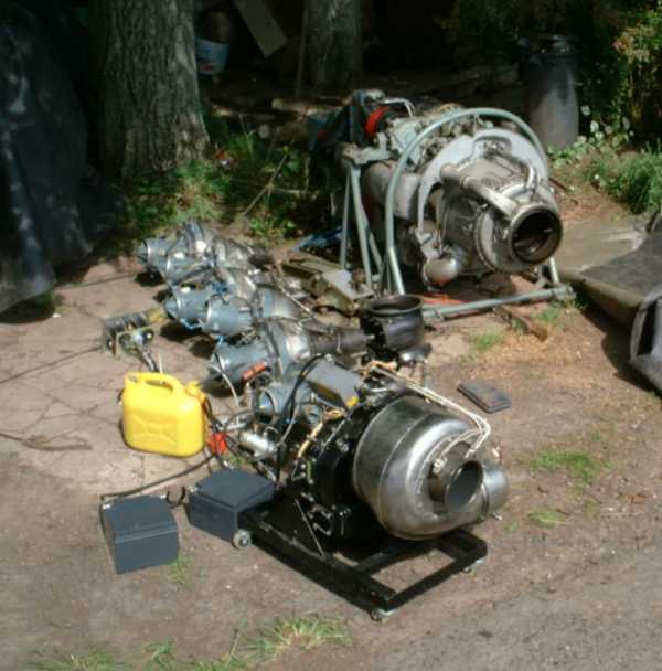 |
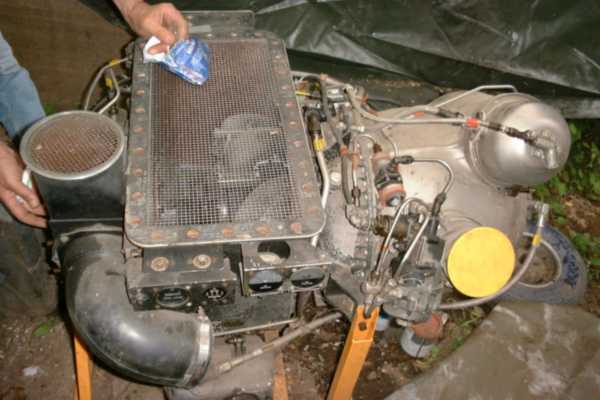
Turbine collection in the dirt... Well, Peters engines have a hard life, they are stored outside and protected from the weather just by a few, strong, water-repelling fabric blankets. In front my GTP-30 is placed since I had it with me to start it up for Peter. The other large engine is the TA-8 and in between the six WR2-6 are sitting.
I started disassembly of the first engine before taking a photo of it still assembled, I will add in a photo of one of the other engines here later. So lets start with the damage.
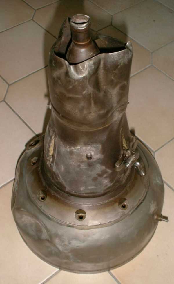 |
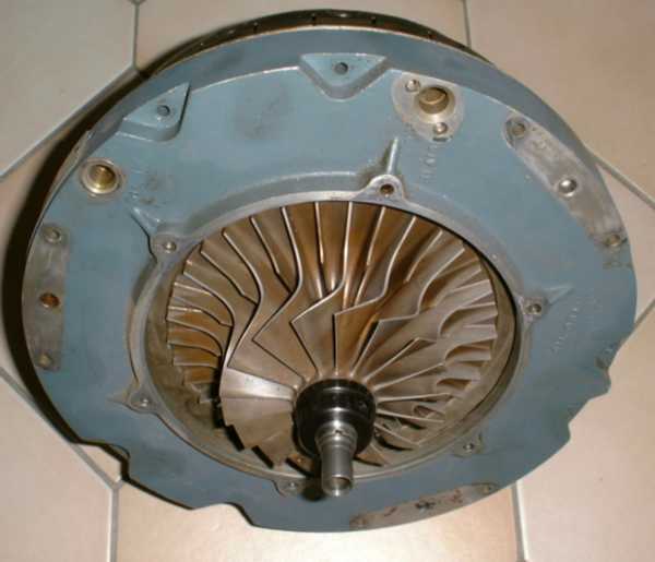
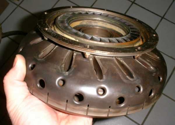
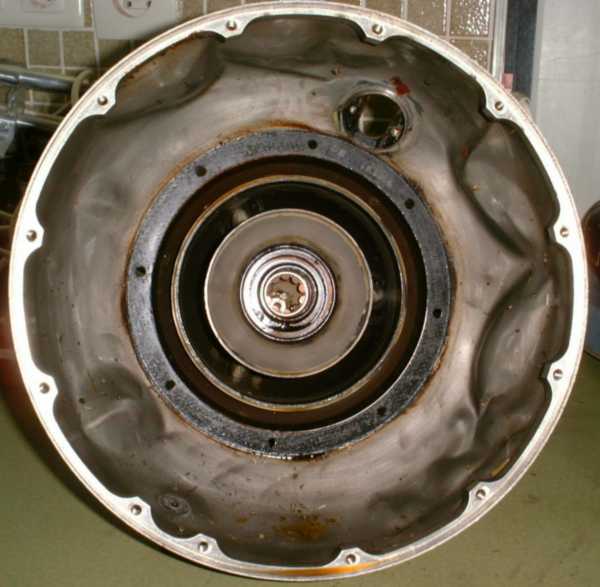
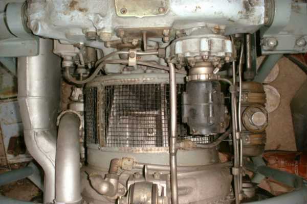
This engine casing looks quite frustrating, especially since it is a very complex piece of engineering. The bad thing is that it is an integral construction and the thrust nozzle cannot be separated from the combustor casing. Not to be bad enough already, this structure also contains the rear turbine shaft roller bearing along with its lubrication system and the turbine wheel shroud. Yet in this specific engine, the latter structure still appears to be intact since the rotor spun freely prior to disassembly. For the first try, Ill simply do my best to straighten out the dents and put this part back into its original shape. Anyway, except for a few tubes, the spark plug and some wiring, this appears to be the single major part that suffered damage.
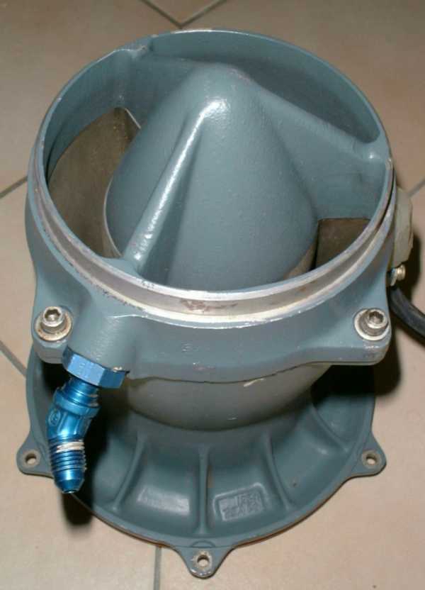 |
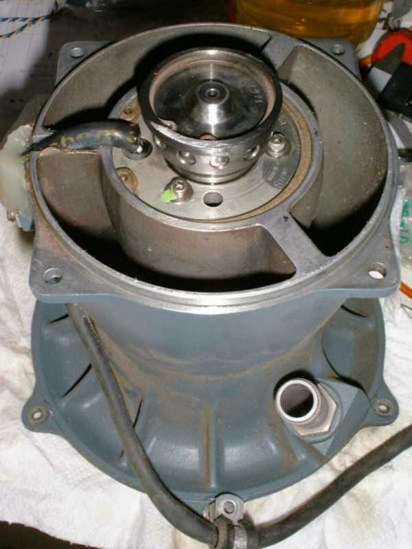
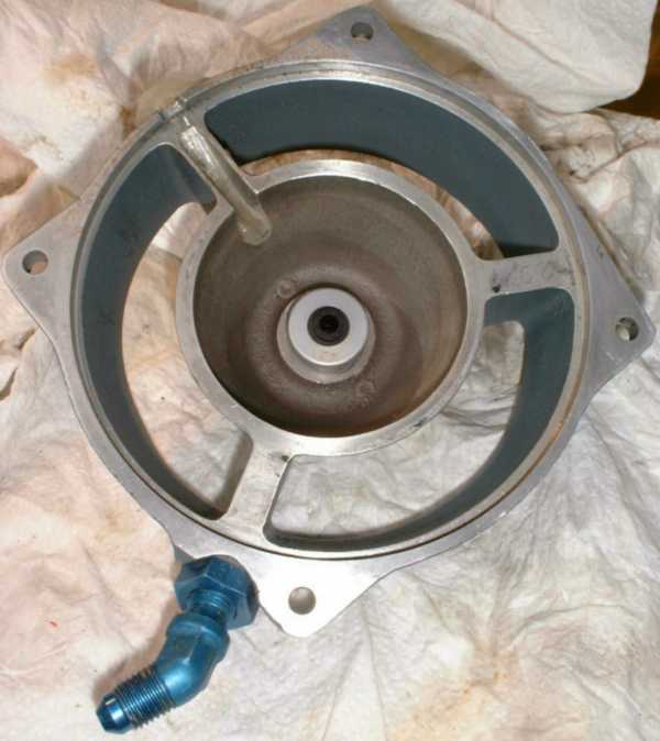
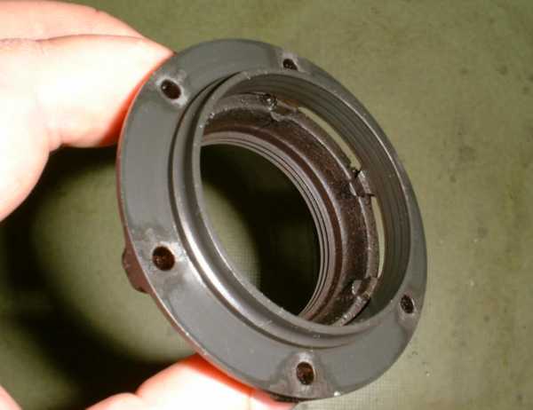
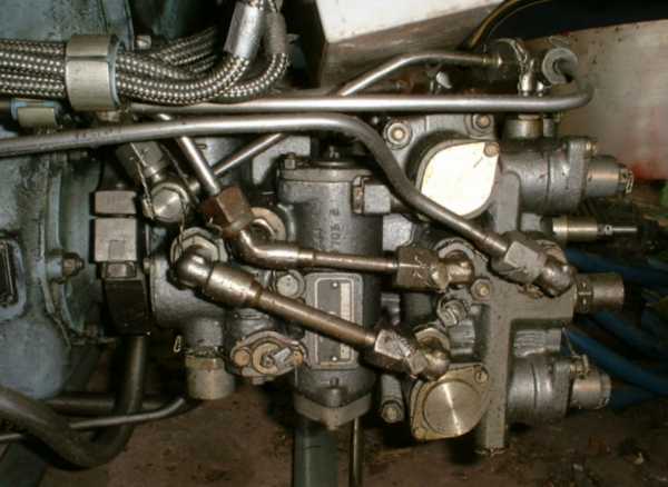
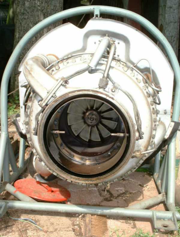
Heres the intake of the compressor shown. Its already cleaned and inspected, no damage on this part at all. The nose bullet contains a three-phase electrical alternator that supplies electricity to the drone systems while the enigne is running. It is directly driven by the turbine rotor via a quill shaft. The alternator is supported by a pair of permanently lubed, axially preloaded ball bearings. In front of the alternator, mounted on the same shaft, theres a governor that reduces fuel flow once the enigne reached 100% design speed. Since the engine features centrifugal fuel injection, supplied through the hollow shaft as pioneered by Turbomeca of France, a governor design like this is quite simple. Further down on this page, the details of this governor are shown.
 |
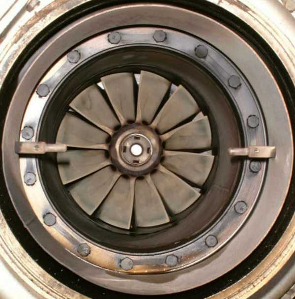
This must be the compressor wheel with most vanes Ive ever seen. It has got seventeen long and seventeen short vanes on a wheel of only 150mm diameter. The vane tip hight is quite small at 7mm. Its quite amazing that a compressor as small as this is suposed to deliver 1kg of air per second at 61,000 rpm and produces a pressure ratio of 4.1. As can be seen, except for a little dirt, the compressor is in great condition.
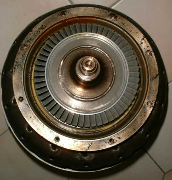 |
The business end of the enigne core. This turbine wheel aslo looks as if it was brand new except for the traces of carbonized oil. Theres no erosion or another trace of wear at the turbine wheel or at the visible parts of the NGV.
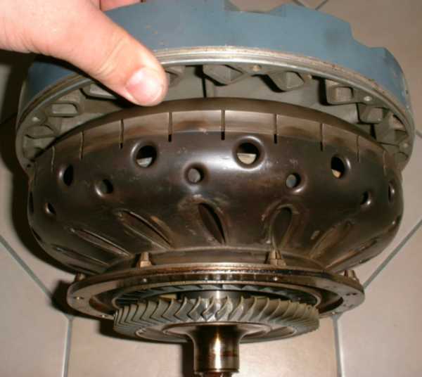 |
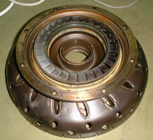
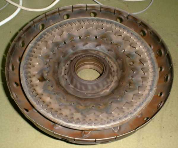
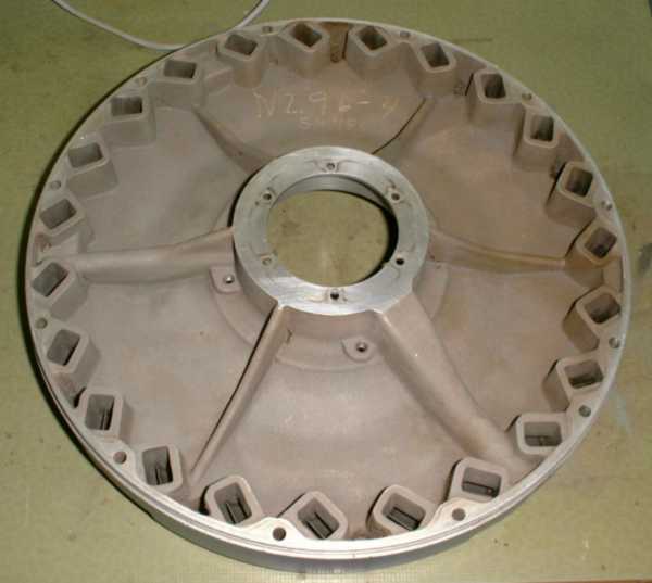
Here the engine core is shown from the side. Since the engine has got a disc combustor, the rear half of the liner is supported by the turbine casing while the front is bolted to the compressor casing. Another quite interesting feature of the compressor is the arrangement of the diffuser as 23 separate ducts, each one ending in a rectangular cross-section to the plenum chamber.
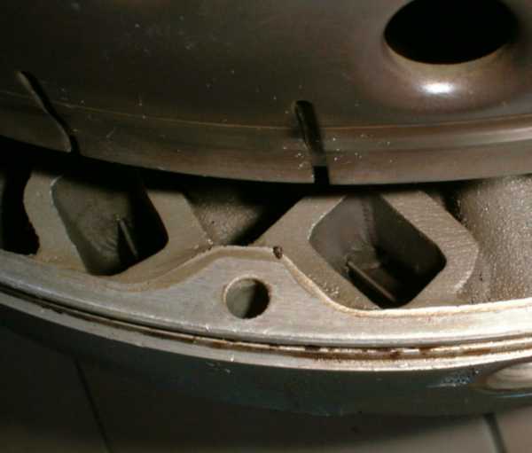 |
One very amazing detail of the diffuser is that each of its channels has got a cascade vane located at the right angle turn to reduce eddy losses there. Alltogehter this light-weight alloy casting is a very complex piece of engineering and Im sure the efficiency of this compressor is very high. Im already curious of what I will find when I separated the diffuser from the rest of the engine...
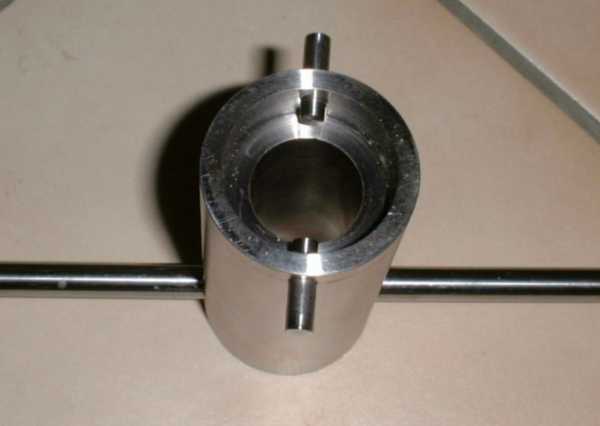 |
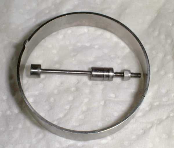
...and this leads us here: I had to make this tool to be able to remove the compressor nut. It is a round nut with bores on two opposiong sides. I can pull the pins of this wrench, slide it on the nut and then push home the pins and the tool is engaged. At least thats how its supposed to work. As yet, Ill have to find out if this tool is strong enough to remove the nut (or if I will shear the pins...). Anyway, since Ive got three of these engines, I thought it might be a good idea to make such a wrench.
 |
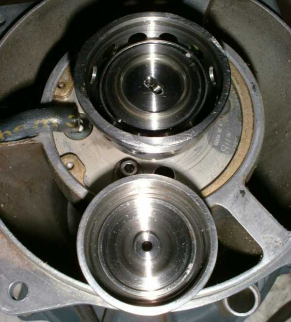
This photo shows the compressor intake with the nose cone off. The circular part at the top of the shaft contains the governor. The following photos will explain its operation. Fuel is applied through the central bore of the governor with a certain (...yet to be figured out...) feed pressure. Yet I think it wouldnt need to be more than perhaps one bar - the centrifugal injection system helps us here. The large, angled stud at the lower periphery of the compressor intake is the start air connection. Compressed air is blown onto the compressor vanes to initially start the engine turning. Considering the power of this unit, I guess a lot of pressure will be required and quite a high mass flow as well. I guess Ill have to add some wider tubing to my compressor if I should ever be in the situation to start this engine.
 |
Fuel is fed to the governors central bore through one of the struts of the nose cone and then through a hollow carbon seal. I guess this part is one of the life-limiting components of the engine since at a relative speed of more than a thousand revolutions per second, the carbon will quickly wear. Yet, currently it still apperars to be in quite good shape.
 |
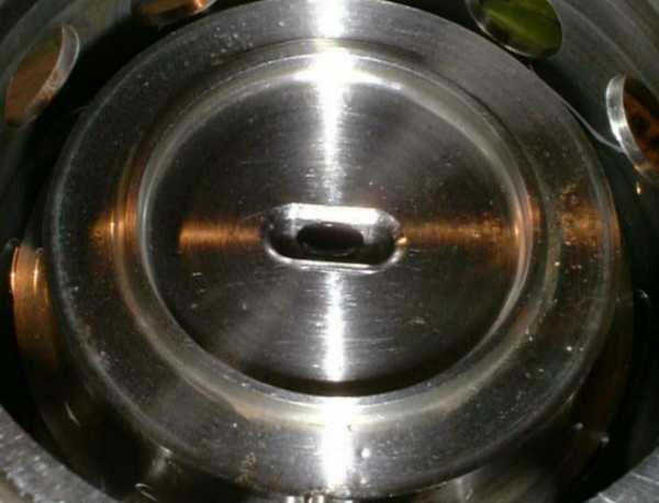
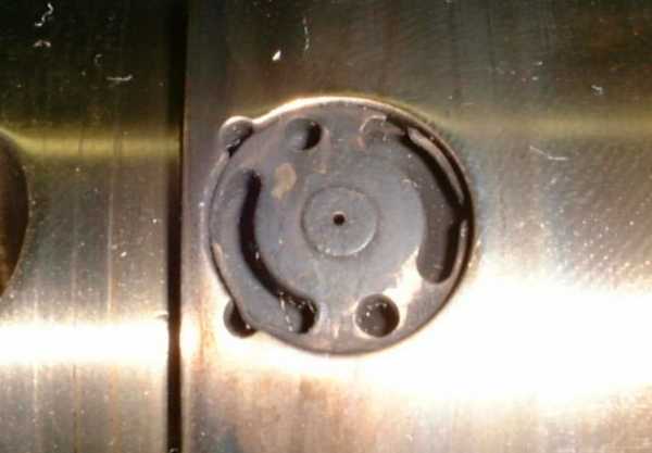
This photo shows tha governor with the cap removed. When assembled, theres an O-ring gasket between the recesses of the governor body and the cap so fuel has to enter through the oval pocket at the centre of the governor body. Around this body, theres a cylindrical spring, extended a little by a pin at one side and pressing onto the control piston at the other.
 |
Here this spring and the control piston are shown. The thick part at the left-hand side of the piston is the flyweight, while the central area with the two recesses is actually the control area. The locknut at the right, threaded part acts as an adjustment weight to set the actuating speed of this arrangement to 61,000 rpm.
 |
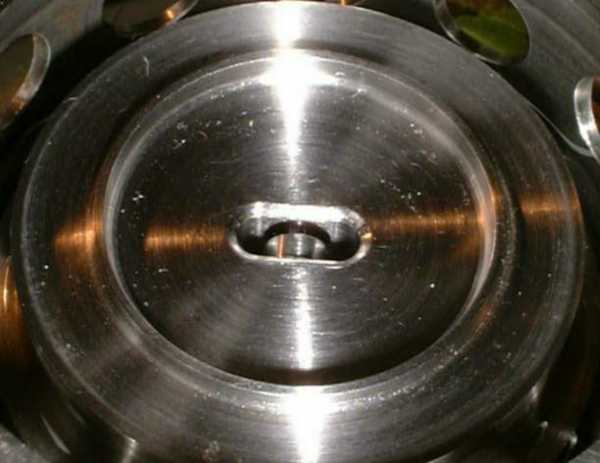
The piston bore in the governor body runs through most of its length and connects the oval pocket to an internal cavity (hardly visible in this photo, sorry) that discharges into the hollow shaft to the power section of the turbine. Theres also another small bore (probably less than a millimeter) that admits always a certain flow of fuel to the combustor, independent of governor condition. This is the minimum flow orifice that prevents the combustor from flaming out if the governor should overshoot and close down the fuel flow completely.
 |
Thats almos the same as the photo above, only this time with the control piston in place. This is the fully open position. When the enigne reaches design speed, the piston starts to move up (at least that would be its direction in the above photo, actually its rotating of course...) and close the orifice to the hollow shaft cavity. I must admit, this governor is intriguingly simple. Yet Im not sure if the arrangemet will allow to throttle down the engine by external means of fuel flow limiting devices. It could well be possible that it simply flames out.
07/03/2004 Since I had to clamp the engine rotor in a large vise to undo the compressor nut, and I havent got one big enough at my place, I went to my parents place and did the rest of the disassembly job at my dads workshop. Sure enough, the specifically built compressor nut wrench worked well. Yet it was quite amazing how tight the nut was. Unfortunately I dont know the right torque when Im going to tighten it again. I guess good old look and feel has to suffice...
 |
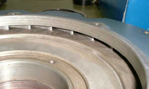
This and the next photo show the rear member of the combustor liner/NGV assembly. Its a quite complex welded sheet metal / cast construction. I really wonder that this effort is taken for an engine that I always considered to be a disposable unit. But my findings during further disassembly will show that these engines are probably being overhauled and re-used.
 |
As clearly visible, the condition of this rear combustor liner is very good and the dents to the auter casing havent affected the internals.
 |
The front combustor liner is basically a half-doughnut shaped sheet metal piece in which some louvres are cut/pressed. Its funny that obviously one crack has been welded during a previous overhaul. Its not that good visible in the photo above, its located at the 10 oclock position in the outermost row of louvres.
 |
Thats a shot of the whole combustor/NGV assembly, both halves joined. Here it becomes clear how small actually the complete combustion chamber is. It can be considered to be a shrunk version of the Turbomeca Marbore combustor which resembles the same principle but I think was earlier designed...
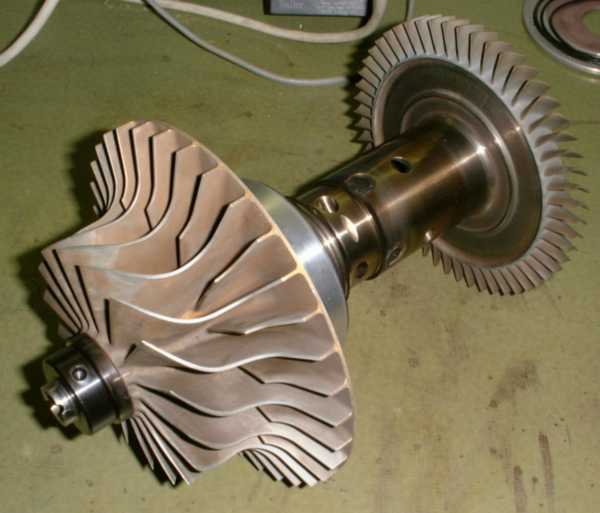 |
The complete rotor with the compressor bearing support in place. Its a very rigid construction with a very large diameter hollow shaft as to offer a high enough resonance frequency. Here are a few details on the wheels:
Compressor outer diameter 150mm, vane tip hight 7mm, inducer diameter 97mm, vane count 17 full and 17 half (quite a lot for a compressor of this size).
Turbine blisk outer diameter 130.5mm, hub diameter 102.5mm, blade count 53 (once again a whole bunch...).
The engines specifications are approximately:
Thrust: 56daN
Thrust-specific fuel consumption:1.25 kg/daN/h
Air mass flow: 0.91kg/s
Compression ratio: 4.1
Total diameter: 280mm
Total length: 500mm
Dry weight: 13kg
Time to overhaul: 25h (not too sure about this)
These figures are very similar to larger engines of the same principal design (for instance the Turbomeca Marbore). Its quite an achievement of the Williams engineers to rech the same efficiency figures that much larger engines with usually better component efficiency have. I guess the tradeoff for this is the low TBO for this engine. But hardly an engine powering a drone will ever experience this age...
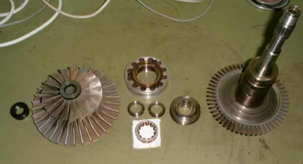 |
The rotor disasembled. Ive never seen a ball bearing with a split inner race in an engine as small as this one. These bearings are very expensive to make and require very good matching of the outer and the two inner race members. This bearing appears to be almost in mint condition.
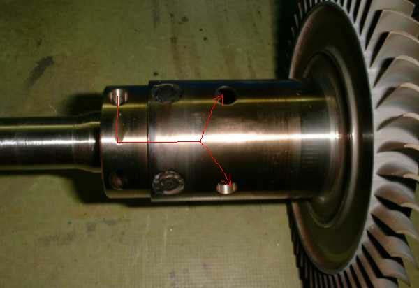 |
Here the centre section of the turbine shaft is shown. The shaft itself is hollow and guides air to the labyrinth seals located all around the bearing surfaces. The red arrows show the path of the air. The big holes next to the recess of the shaft are drilled at an angle so that compressor delivery air is rammed into them. Inside the shaft, between the four rotating fuel nozzles, there are axial bores towards the rear, being drilled parallel to the turbine rotor axis. They guide the air into the large cavity of the shaft, next to the turbine wheel. Since the turbine wheel itself is closed at the back, this machining must have been done before the turbine wheel and the shaft were permanently attached to each other. Close to the turbine wheel, a change in colour of the metal is visible. I guess at this position, the two members were either electron beam or friction welded.
 |
Heres a close-up of one of the four fuel injection nozzles. Fuel enters through the hollow compressor shaft, then it is accelerated by the rotating radial galleries in the shaft to reach the fuel nozzles at very high pressure. The relative movement of the fuel droplets to the air further aid atomisation which must be very good since no soot was to be found in the engine at all.
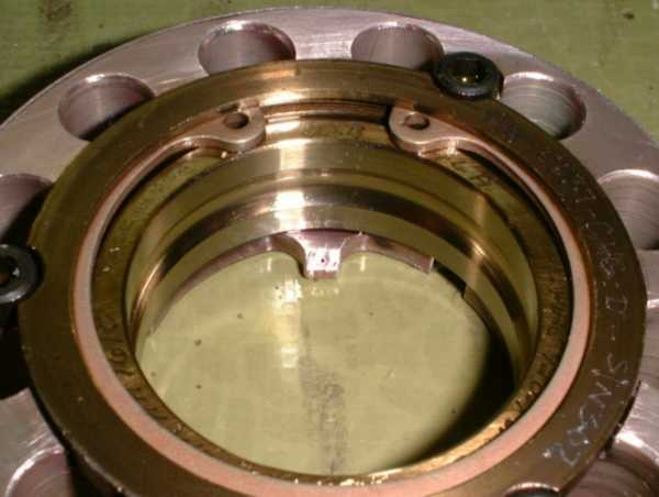 |
Here the compressor bearing out er race is shown, mounted in its support. The small nose at the 12 oclock position has got a tiny bore which injects the lubrication oil into the bearing. The engines lube system is of the total loss type. Nevertheless, the oil leaves both bearings through dedicated return ports and is vented to the atmosphere through a short piece of pipe. Maybe the engine was initially designed to operate with a circulating lube system. Else many of the labyrith seals could have been omitted and the oil to be disposed of just mixed with the compressor air inside the engine.
 |
One of the labyrith seals, this one made from cast iron. Notice the gap between the two sealing areas where compressor air enters as a buffer.
 |
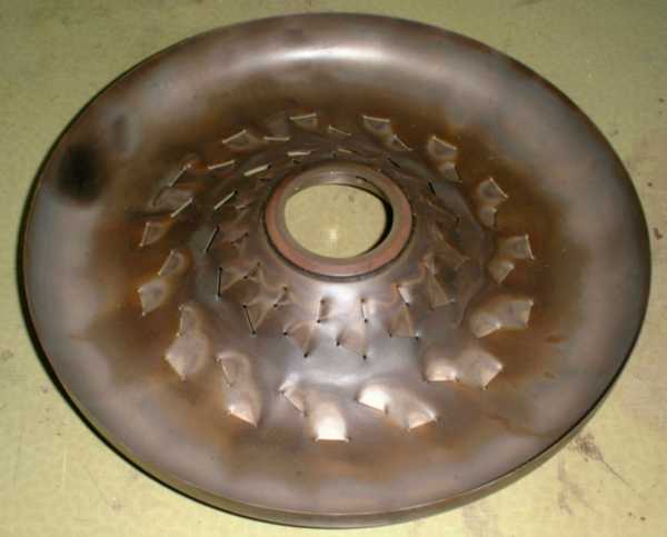
A rear view of the compresor diffuser with the discharge ports of the 23 discrete diffuser ducts. As explained above, each of these ducts has got a cascade vane to help directing the compressed air around the 90 degree elbow into the axial direction. It appears that these cascade vanes arent cast in light metal alloy but are made of pre-formed steel sheets that have been included in the dye prior to casting. This must be one of the most complex parts ever to be cast for such small gas turbine engines.
 |
Here the entry into the small diffuser channels is shown. The surface quality of this component is very good, even tough machining inside the diffuser ducts is hardly possible.
 |
One more view of the dented combustor housing. Here the turbine shroud and the rear bearing are visible as well as the spark plug mount. Oh well, thats another story since Ill need to find a suitable spark plug in order to be able to start this engine...
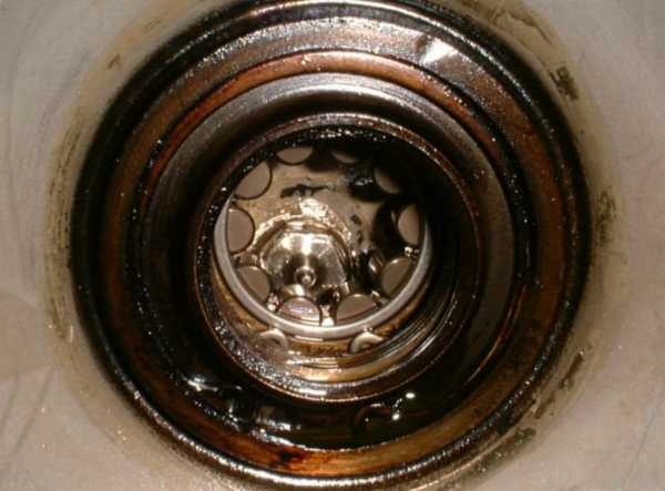 |
And the last photo for now - the rear bearing less the inner race, which is more or less permanently mounted to the shaft at the rear of the turbine wheel. Since this bearing as to compensate for some axial movement of the turbine rotor (thermal expansion, load changes), a cylindrical roller type has been selected. Behind the complement of rollers, the oil injector can be seen at the seven oclock position. Some carbonized oil has settled around the seals of this bearing cavity, but the deposition isnt very thick and it can be removed quite easily. Tomorrow Ill have a go at removing the dents from the turbine casing. If Ill be successful, reassembly will be next. So stay tuned if you please :-)
_________________________________________________________________________
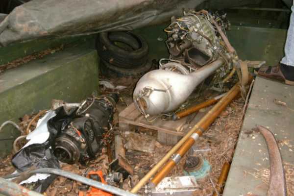
Ok, here Ill just place a few photos of my visit to Peter without writing a lot of text. Further down, theres a video clip of an ultra-hot hung start of his TA-8 engine.
 |
 |
 |
 |
 |
 |
And here is the promised video clip of the hot start (1.7MB, DivX as always). Unfortunately the angle the camera was placed doesnt show the turbine wheel itself, but please watch the left-hand one of the two EGT thermocouples... Also, the engine makes quite a funny noise when casting down to a halt. Otherwise, I think this engine produces a really beautiful sound, probably it has got a multi-stage compressor, but Im not too sure about this.
 |
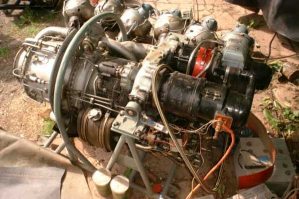
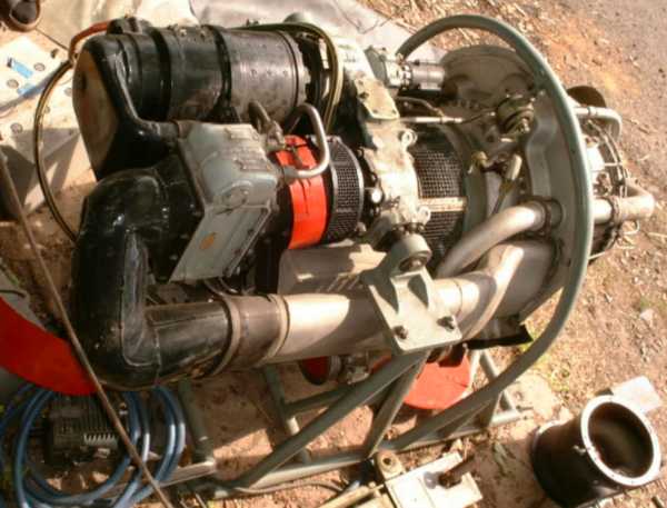
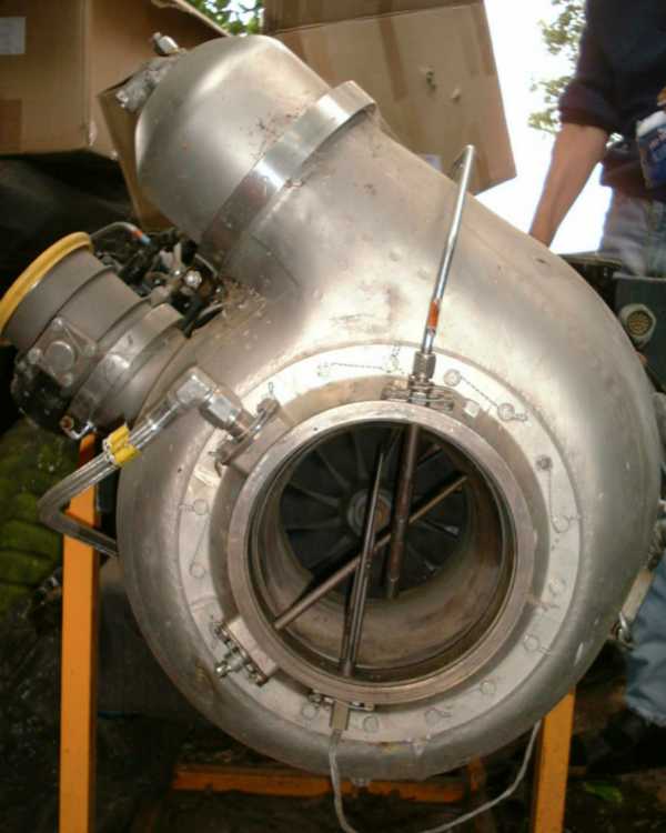
If you know the colour of a turbine wheel that has operated at usual (healthy...) themperatures, you know that this one has been waaaay too hot. Its almost white or a very bright grey, a sign for being severely overheated. This is to blame to Peter, who thought his single, strong 12V battery will suffice to start a turbine engine designed to operate on a 28V system. Usually 24V (two 12V car batteries in series) will do, but since the TA-8 unit appears not to be equipped with any hydromechanical EGT limiter, and Peter has neither an EGT gauge nor an RPM indicator istalled, starting this engine is close to playing Russian Roulette. Im not too sure if taking the engine up to governed speed ever again would be such a good idea, not knowing if the turbine wheel has suffered metallurgical damage from the severe overtemperature (he practiced this treatment several times before...). Anyway, Peters turbines have got a hard fate...
 |
 |
 |
 |